In spite of the improvements in efficient Class D switchers, watt-sucking Class A power amplifiers continue to attract high-end audiophiles. The breed remains as popular as ever—and why not? Any product of our school system knows that A is better than B, or C or D...
I get quite a bit of email, and it is filled with general questions about compatibility of components, the sound of different products, how high the cables should be lifted and so on, but there is a topic which comes up a regularly: "Where does this amplifier leave Class A?"
It is generally understood that ordinary Class AB amplifiers operate Class A at some low power level and then fall to Class B at higher levels. Being the most linear operating region, it is understandable that we want an amplifier in Class A at high power levels too. Unfortunately, the class is very inefficient, generally idling at twice the maximum output power, like a Ferrari sitting at the curb with the engine at full rpm. For a little 10-watt amplifier, this is not much of a problem, but for a 500-watt amplifier, Class AB starts to look like an attractive compromise between quality and efficiency.
Class A being so inefficient and yet so desirable, various methods have been developed whereby circuits controlling the class of operation can adjust the amplifier's operation in response to the signal. It is possible to maintain current conduction of the all the devices in the output stage of an amplifier so as to technically be "Class A," but operate more efficiently. These circuits have been variously called "Dynamic Class A," or "New Class A," or "Non-Switching Class A."
Audiophiles have historically viewed these approaches with some suspicion, and these days traditional Class A designs are often referred to as "pure" to distinguish them from these "trick" Class A amplifiers.
The subject is still interesting, and so here I am, writing about it again, eleven years after the original article. Despite the probability that you, gentle Positive Feedback reader, will already know something about Class A operation, I will provide a brief of technical summary:
Class A is where all the gain devices (tube or transistors) in the circuit participate in the amplification of the signal at all times. This also means that they are conducting current at all times. A fine example would be the very simple single-ended Class A circuit with only one device:
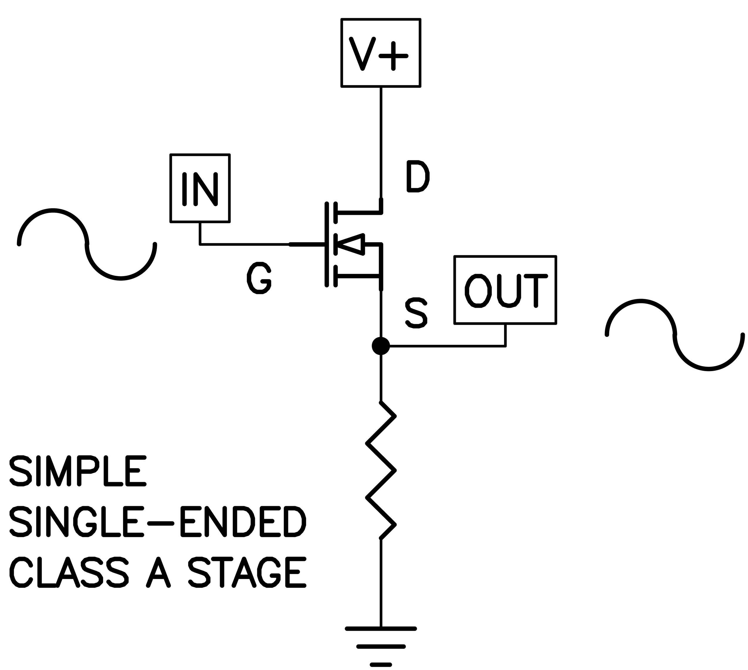
Here we have a single transistor which provides current gain and drives a resistor.
You can see the three pins of this N channel Mosfet labeled for Drain, Source, and Gate. Current flows from the Drain to the Source (in case you are wondering, for historical reasons current is the opposite of electron flow) and is controlled by the voltage between the Gate and the Source. This particular circuit is a "follower," where the input and output voltage is the same, and it delivers current amplification.
The linear limits of this particular circuit are the positive supply V and Ground. In between, the transistor conducts current linearly in Class A. It leaves Class A when the circuit "clips" at the extremes and is no longer linear. There are other examples of single-ended Class A circuits, but they all resemble this in some way.
This particular case is very simple, and has generally low distortion, but is also very inefficient. Typical single-ended amplifiers will have an efficiency of less than 25%, which means 10 watts of Class A will idle at more than 40 watts.
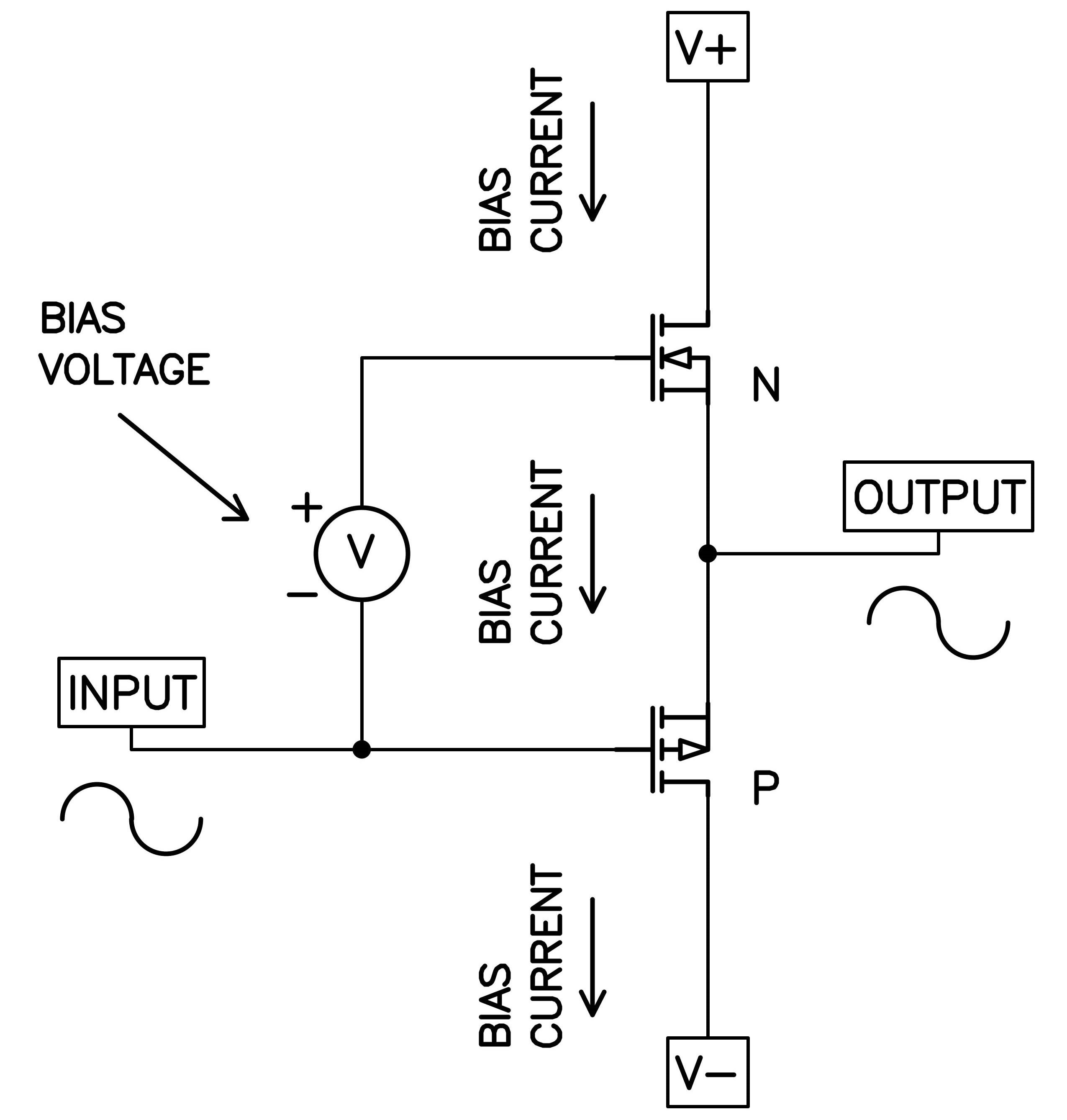
With a little more complexity, we can arrange two gain devices differently so as to operate in push-pull mode. The simplified circuit for such an output stage looks like this:
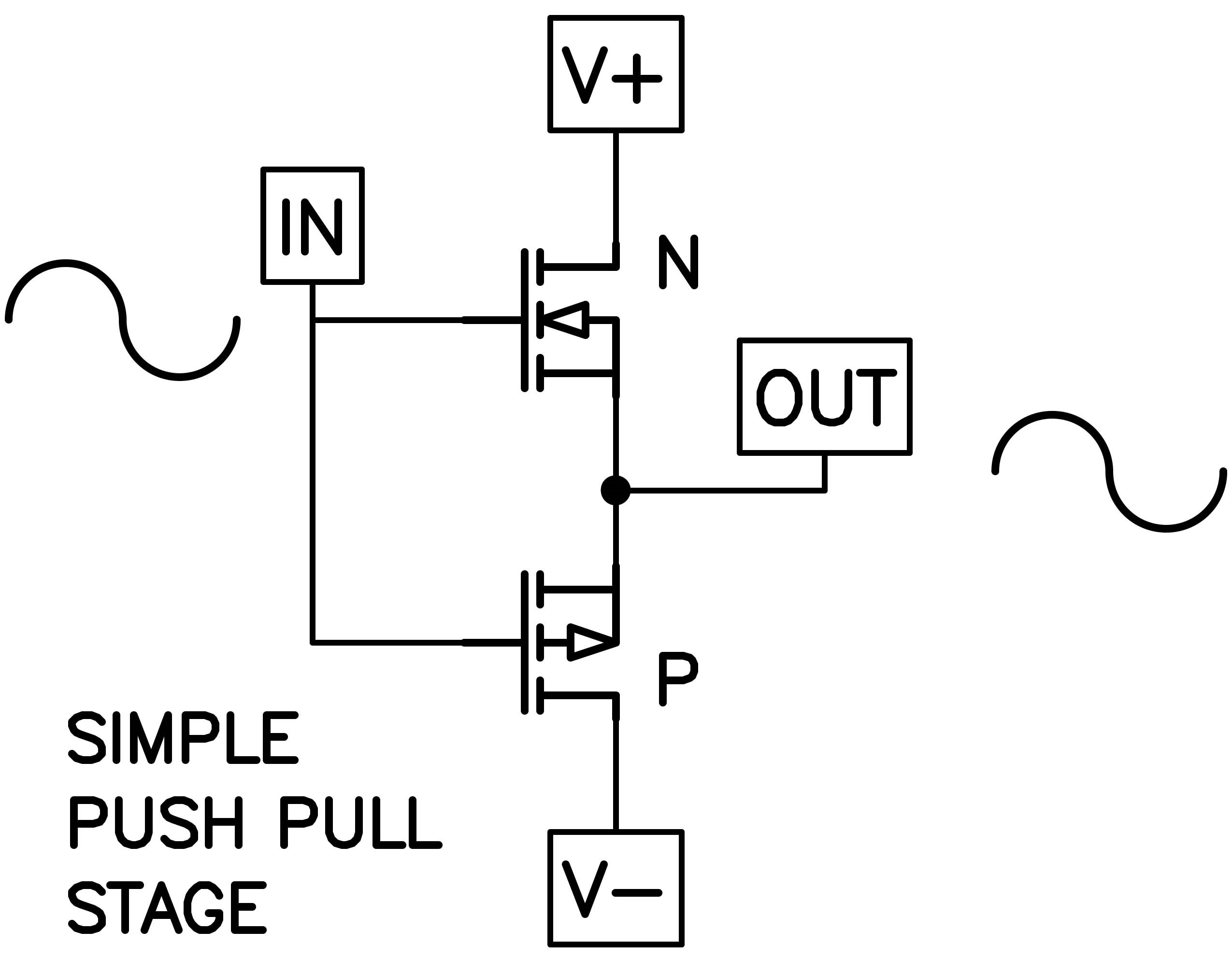
In this case two power transistors operated as followers where the output voltage equals the input voltage, with the amplification being much higher current. Transistor N is attached to the positive power supply and P is attached to the negative power supply. If this was an audio power amplifier, the output would go to a loudspeaker.
When the input voltage is positive, so is the output voltage, and we would look to transistor N to supply current to the loudspeaker from the positive supply. When the input voltage is negative, we look to P to supply current to the loudspeaker from the negative supply.
Audio signal has both positive and negative voltage components and we will see a point at zero volts where the two halves meet. Unfortunately, the transistors we use tend to shut off before they meet at this point and so have a poor transition between them, a dead zone creating a distortion usually referred to as "crossover notch."
In severe cases, the output waveform for a sine wave looks like this:
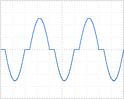
This would be the characteristic of a Class B amplifier, where the two halves of the circuit do not share the load simultaneously. This distortion waveform will ordinarily be corrected to some extent by negative feedback, where the front end of the amplifier will work overtime to compensate for the dead zone. This is not completely effective, as shown in this distortion waveform of a Class B amplifier:
The output sine wave is in blue, and it looks pretty good, but if we focus on the distortion only, we see its ugly shape in red.
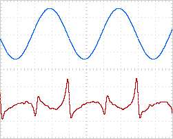
We can fix this up by providing "bias current" to the transistors which creates a region where both transistors conduct current simultaneously, and takes the amplifier from Class B operation to Class A. Like the single-ended example, Class A is where the gain devices are always participating in the amplification by virtue of conducting current. With Class A bias current the distortion of that same amplifier looks like this:
Here is how it's done. Below we see a simple DC voltage source used to provide a bias voltage between the control pins of the gain devices to eliminate the dead zone:
Class A works great but comes at the price of efficiency—traditionally single-ended examples operate at about 4 times their maximum output. Push-pull Class A amplifiers are usually about twice as efficient as that, idling at only twice their rated output power.
For push-pull designs there is a compromise approach available—Class AB amplifiers are hybrids which run Class A at lower power levels and become "Class B" amplifiers when one side of the circuit ceases to conduct current. The level that this occurs at is generally proportional to the the amount of idle bias current. The higher the bias current, the higher the maximum level which is still in Class A region.
The impedance of the loudspeaker has a large influence on the point at which an output stage ceases to be Class A. This is because the class is a phenomenon of current rather than voltage—the transition to Class B occurs at some particular output current, and a lower impedance draws more current.
Here are graphics of the current sharing seen by the above circuit as the bias is increased:
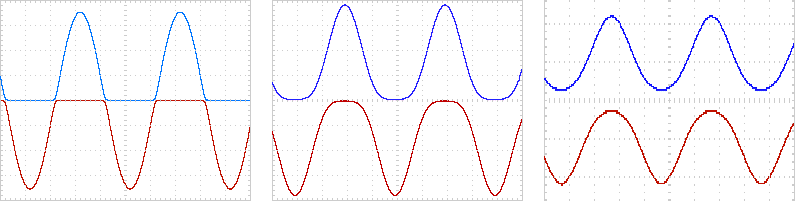
The low bias current on the left leaves the Class A region at a small fraction of maximum power and the middle shows Class A to half power. At right we see full Class A where there is no shutoff for either side (note different scale to accommodate the larger wave).
Perhaps the most important thing about these pictures is the relative smoothness of the curves. As the bias is set to higher values, the approach to cutoff and the transition between the two halves is smoother. This is analogous to a relay race where the best result is achieved when the hand-off occurs when both runners are at speed.
Smoothing the transition is important because it dramatically reduces the high-order distortions which are more audible and annoying. Worse, they are far more apparent at low levels.
Some imagine that the transition from Class A to Class B results in a discontinuity or "Klunk," with gain devices turning on and shutting off while music is playing. This is somewhat the case when the bias is very low and the transition is not at all smooth, but is not really an issue with a decent amount of bias.
It is important to understand that an amplifier doesn't have to be Class A to benefit from higher bias current. High bias current doesn’t just move the Class A transition to higher ground, it offers improvements at all power levels.
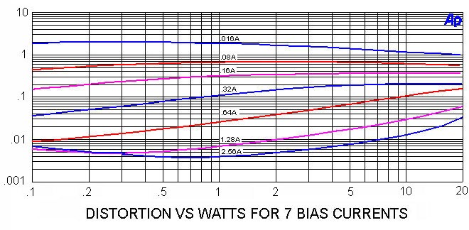
Below we see the distortion of an output stage operated without feedback driving 8 ohms from 0.10 watts up to 20 watts. The top curve with the highest distortion has a bias of 0.016 amps. The next lower is 0.08A, followed by 0.16A, 0.32A, 0.64A, 1.28A, and the lowest distortion curve at 2.56 amps. What we see clearly is that higher bias lowers the distortion at all power levels, and that the distortion is inversely proportional to the bias current.
It is not simply that the distortion numbers are lower, but the characteristic of the distortion is improved in terms of the ratio of lower order harmonics (2nd and 3rd) to higher order harmonics (4th, 5th, 6th and so on)
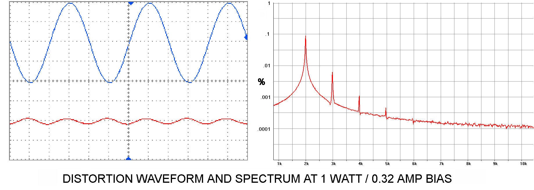
Below we see a distortion analysis with an output stage biased at 0.08 amps. On the left you can see the signal waveform in blue and the distortion waveform in red. The distortion measurement is at 0.67% total, and you can see the harmonic components on the right, where harmonics from 2nd through 10th are prominent.
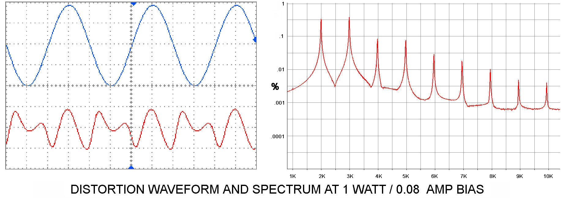
Here is the same test, at 4 times the bias. The distortion total has dropped to 0.11%, but of greater interest, the higher harmonics have been dramatically reduced, leaving a dominant 2nd order harmonic.
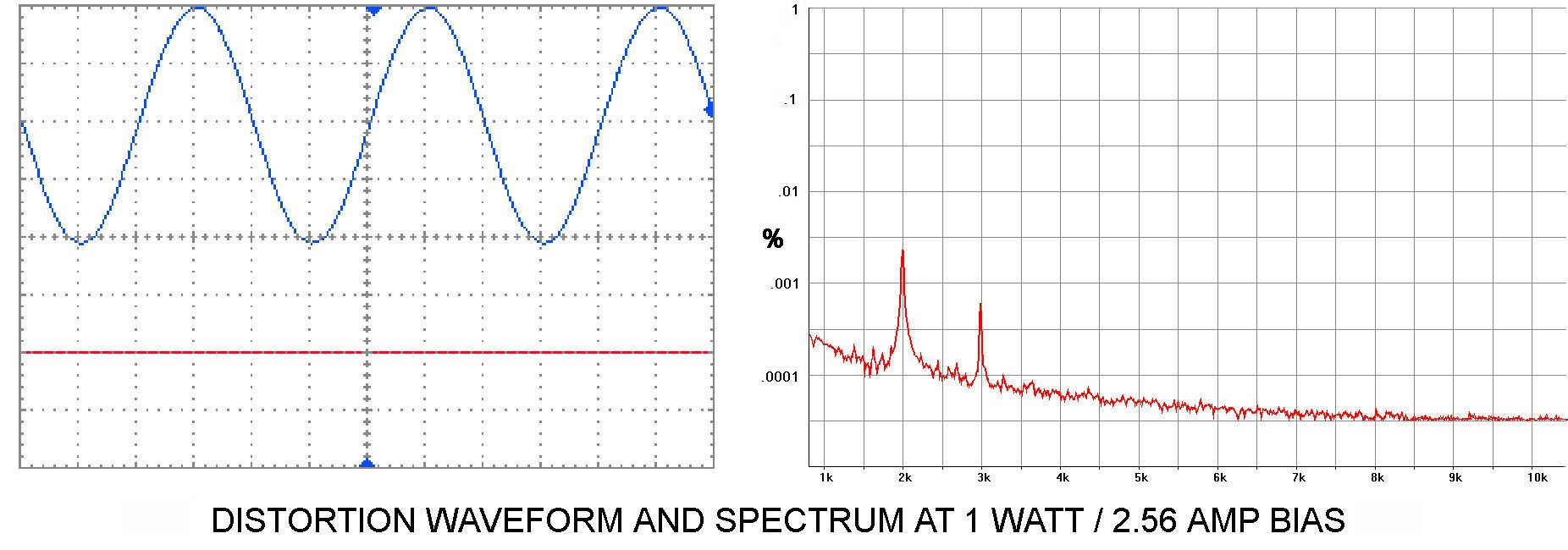
At eight times more bias the distortion drops to 0.004%, leaving nothing to look at on our distortion waveform and only 2nd and 3rd harmonic on the spectrum analysis.
The benefits of high bias current extend beyond simple harmonic distortion measurements—you also get a reduction of intermodulation distortion (arguably more important), and a lower, more consistent output impedance. As a corollary benefit, the heavy hardware required to support Class A operation will show better thermal stability and will deliver better performance into difficult loads.
We can clearly see that a lot of improvement is achieved with a modest bias current. Yes, full Class A is better, but in this case it consumes eight times the energy dissipation at idle. That could be the difference between 50 and 400 watts heating your listening room, possibly making Class AB more attractive.
That takes us back to the question of where the amplifier leaves Class A, as it is a reliable indicator of bias current, and we have seen that the bias level remains important for a Class AB amplifier.
Consumer's guide to Class A
Every once in a while you will see an amplifier on eBay rated at "100 watts Class A" and it looks to weigh about 2 pounds and has heat sinks about as big as your thumb. This represents an obvious case of exaggeration, but the question remains for more respectable products.
So what's an audiophile to do? Imagine that you are concerned about the level of Class A, and looking at an amplifier whose manufacturer specifies Class A at a certain power level, or (more likely) where that information isn't listed.
First off, regular Class A amplifiers tend to weigh about a pound per watt, and they tend to cost about $100 per watt (or more). They all run very warm, if not outright hot. The power ratings usually present the most optimistic figure—into 8 ohms.
The editor at Positive Feedback assures me that a little DIY is appropriate, so:
Here is a test that you can perform if you have one of those power-consumption gadgets (like the Kill-A-Watt(tm)—about $17 from Amazon and elsewhere). Buy one of these and you can read the power draw of an appliance, however you should probably add 25% to the reading, as most of these devices do not read accurately for appliances with a "power factor" less than 1. They work great for electric heaters and such, but audio power amplifiers typically have power factors around 0.8 due to the internal conversion from AC to DC, so multiply the watt figure by 1.25.
The draw of a "regular" Class A push-pull amplifier should read approximately twice the rated power. or example, if it's a two channel amp at 50 watts/ch, then you would be looking to see something like 200 watt draw out of the wall. This is not a precise calculation, and ignores power factor and other losses, but it is plenty good enough for our purpose here. Best to let the amp warm up for a bit before measurement.
If the amplifier draws less than this, but still runs nice and warm, then perhaps it is a highly biased AB amplifier, also referred to as A/AB. No shame in that—earlier we have seen curves showing that an amplifier that falls short of full Class A at rated power is nearly as linear.
You can get a thumbnail estimate of the level this amplifier will leave Class A by knowing its rated output watts and also the idle watts drawn out of the wall.
Pa d * Pd / Po / 4
Where Pa is the Class A power rating in Watts rms, d is the Watts drawn from the wall outlet, and Po is the maximum output of the amplifier in Watts rms
Here is a simple example for a 100-watt push-pull amplifier.
100 Watts Class A = 200 watts * 200 watts / 100 watts / 4
If you have more than one channel, then you simply apportion the power draw, as in the example of a 50 w/ch Class A which draws 200 watts for two channels:
50 Watts Class A = 100 watts * 100 watts / 50 watts 4
Just remember that these calculations are approximate.
If your AC power draw is less than twice the rated output, you can estimate it by the same formula:
Pa d * Pd / Po / 4
Where an amplifier channel is rated at 100 watts, but draws 50 watts at idle:
Pa 0 * 50 / 100 / 4 = 6.25 watts
The rate at which Class A falls is the square of the ratio of rated maximum output and the idle draw, so we can have a case where the heat sink is still warm, but the Class A wattage figure is quite low, for example: 1/4 the bias = 1/16 the power.
Still, the good news is that high bias current floats all boats. Class AB amplifier with a decent bias current still offers fine performance. Something like the X-600.5 Class AB amplifier biased at 1.8 amps will operate Class A to 50 watts rms, but also enjoys performance improvement at all powers right up to its 600 watt rating.
In conclusion, I should not have to point out to this audience that all this is supposed to simply be in the service of the quality of sound that you experience, and this is a personal and subjective thing. My own observation is that Class A amplifiers sound better than the alternatives, but you should let your own ears be the judge.
All images courtesy of Nelson Pass.