

Nelson Pass: a portrait. Sea Ranch, CA, 2018. (Photograph and image processing by David W. Robinson)
This piece was originally presented at the 2019 Burning Amp Festival but was hampered by problems with the projection system. It has been rewritten for Positive Feedback....
Introduction
I don't need to tell you that audiophiles tend to be obsessive about parts. Capacitors, wire, resistors, transformers, connectors... I make no criticism—my favorite parts are the gain devices, the tubes and transistors that amplify the audio signal but also leave their imprint.
I entered the audio business about fifty years ago when transistor amplifiers had just come to dominate the market and most designers were devoting their talents to meeting just two performance goals: High power and low harmonic distortion, and it was largely being achieved with cheap circuits that used lots of negative feedback.
There were a few who disagreed with this approach—here were Bart Locanthi's comments in the white paper describing the JBL SA-600 amplifier:
"An amplifier should be designed for low distortion and wide bandwidth without feedback. Negative feedback is then added to make an already good design perform even better; it is not used to "clean up" problems in the basic design."
The approach of using fewer, more linear gain stages with less feedback became more popular in high end amplifiers after it was decided that "slew-induced" distortion and "transient intermodulation" distortion was maybe a factor, caused by lots of feedback and limited bandwidth. As complex high-gain amplifiers tend to be slower, the obvious solutions were simpler, faster, more linear.
Eventually circuit simplicity became a desirable quality in itself, an example being the resurgence of single-ended Class A Triode amplifiers without feedback. The logic is simple: When you have multiple gain stages in series, the distortion not only increases along the way, but becomes more complex and audibly more annoying.
Consider a minimalist two-stage amplifier. When a tone goes through the first stage with a 2nd harmonic character, and then the second stage with 3rd harmonic, the result is also small amount of 6th harmonic, and is on its way to becoming unmusical. How about an amplifier with five stages? I actually have a schematic of a commercial amplifier, no longer on the market, with nine gain stages. I like to think that the designer was paid by the part....
On another track, higher power transistor amplifiers were developed that used more local feedback with multiple gain stages to achieve the desired results. Often this was simply the insertion of resistance in series with the Emitter or Source pins of the transistor. Called Degeneration, this is still a popular approach.
There is good reason - in Bipolars, degeneration helps to limit gain, stabilize the DC operating points, equalizes the current sharing between parallel devices, and can also lower the measured distortion. And if you want reliability, degeneration is your friend.
However, in the last ten years I have noticed that there is some listener preference for FET circuits operated without degeneration. Some listeners can tell the difference and prefer circuits without the resistor. The best of these, Joe Sammut, formerly of Threshold, Krell, and finally Pass Labs, could spot this in blind testing and was adamant about the difference, so I began seriously developing undegenerated amplifier circuits. Over the last ten years the results have been the SONY Commemorative VFET amplifiers, three First Watt SIT amplifiers and recently the XA-25 amplifier from Pass Labs.
Eliminating degeneration from transistor gain stages is not necessarily a trivial exercise. Bipolar transistors in particular are very sensitive to temperature, and because of their very high gain tend toward "runaway" bias in push-pull circuits, as well as "current hogging" when operated in parallel. Bipolars may not be the ideal candidate for this in any case, as shown later where a small amount of resistance might offer some improvement.
FETs of various sorts are less problematic, and for some we can even find operating points where the temperature coefficient is near zero, but it is deep into the Class A region. Tubes are comparatively easy, and are routinely used without degeneration. It's tempting to imagine that this could be factor in their popularity among many audiophiles.
Meet the players:
Tubes and transistors are valves that control the flow of electrons. Like a nozzle on a garden hose, they have three elements: where the water goes in, where the water comes out, and a lever that controls the flow. In a Tube, that lever is the Grid, in a Field Effect transistor (FET) it is the Gate, and for a Bipolar transistor it is the Base. In all cases the control of electron flow is dependent on the voltage between the control pin and one of the other pins - the Cathode, Source, or Emitter pins respectively.

Here you see the venerable Triode tube and both polarity types of the Bipolar transistor,
MOSFET and JFET. The N and P types are transistors which work the same way, but the voltages and current flow are reversed. In this universe the tube has only one polarity, the P version requiring anti-electrons for its operation.
Tubes, FETs and the Square Law
Tubes and FETs have what is known as a square law character - the current through the device is a function of the square of the control voltage. For a tube it means that the electrical current from Plate to Cathode depends on the control voltage between the Grid and Cathode. For the FETs the current from Drain to Source depends on the voltage between the Gate and Source pins.
The gain of a square law device increases linearly with current, resulting in an character in which the current itself is proportion to the square of the control voltage, as seen below:

A truly linear device would have a straight line in this graph. As it is, if we pass a single-tone sine wave through this device, the resulting output would contain the original tone plus some second harmonic distortion at twice the frequency.
The Exponential Bipolar Transistor
Unlike Tubes and FETs, the venerable Bipolar transistor has a transfer curve which is exponential, that is to say that the current is proportional to e raised to the power of the control voltage. This is a substantially sharper curve, resulting in higher gain, but with greater non-linearity and more complex harmonic components.

The Base pin of a Bipolar transistor conducts current like a diode, and is often described as having current gain. As a purely current gain device, the linearity of the Bipolar transistor is not too bad, but for audio we are usually better off thinking of it as a voltage-controlled part with a low input impedance.
Single-Ended Operation
The simplest common use of these gain devices are as single-ended Class A amplifiers, either as having just current gain or current and voltage gain. With just the current gain, they are used as followers where the output voltage is the same as input but at a much higher current. With voltage and current gain, the output voltage is increased as well, but with inverted phase.

The devices with voltage and current gain are called Common Cathode/Source/Emitter, respectively, and the followers are Common Plate/Drain/Collector.
All of these examples will have a significant amount of 2nd harmonic distortion. In the case of the followers it is reduced because the gain is unity—we would say the output and distortion are degenerated by the resistor in the circuit.
You can adjust the single-ended circuits with voltage and current gain by adding resistors as shown below:

The addition of these resistors creates local feedback and lowers the gain of the circuit, as well as the distortion, however they slightly increase the higher order distortion, primarily 3rd harmonic. Much of the time the benefit of single-ended degeneration is worth it, as the downside is not too steep and it is simple to implement.
Push-Pull Operation
Distortion can be greatly reduced through push-pull operation, where pairs of N and P transistors deliver a complementary characteristic. To the extent they have opposite but matched behavior this will suppress the 2nd harmonic distortion, leaving a 3rd harmonic characteristic.

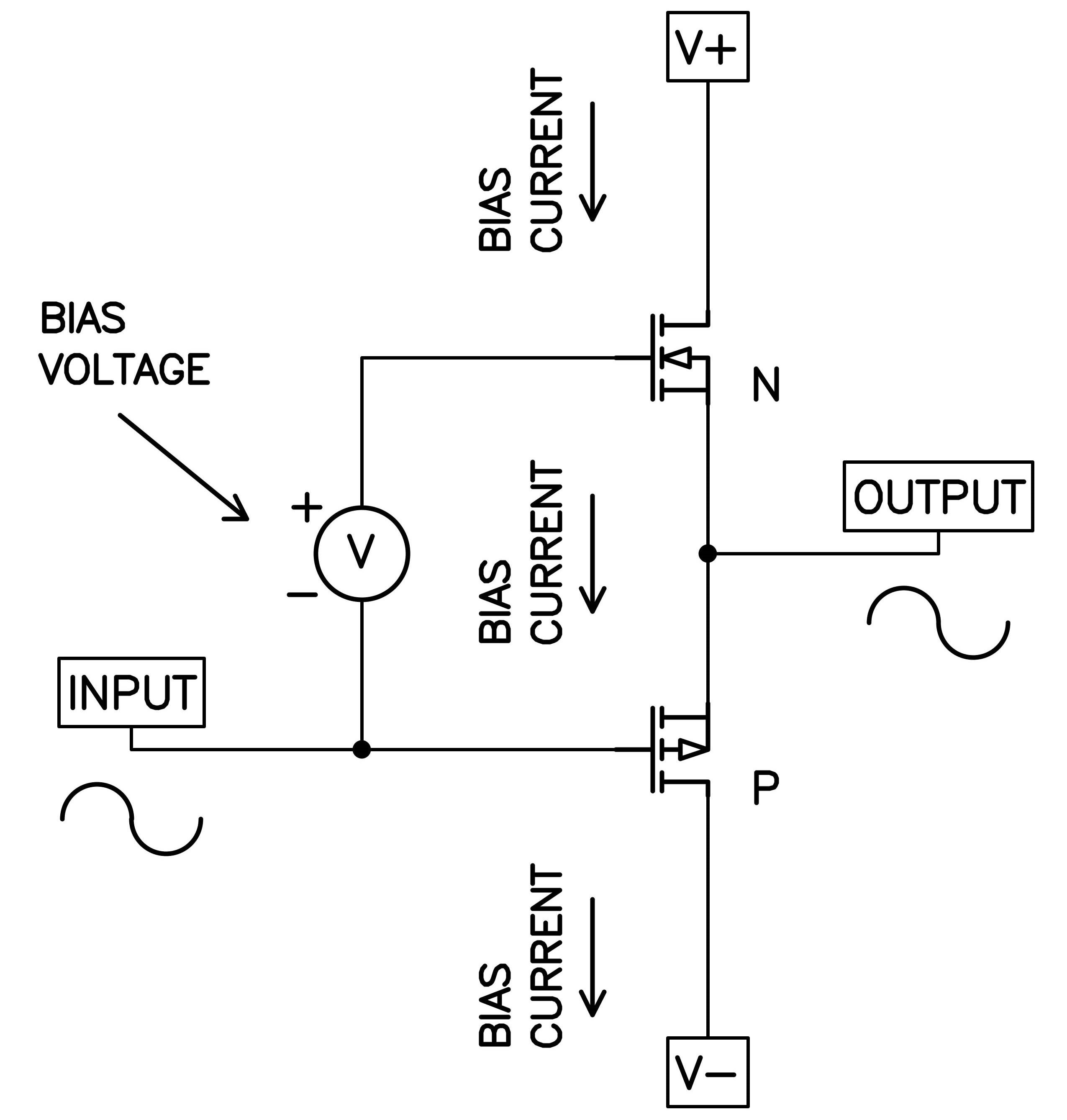
Push-pull is not limited to opposite polarity parts, otherwise it would not be possible to do with tubes. You can also use identical devices in push-pull operation, one example being these examples of differential pairs:

This is not the only such example, and operating push-pull with like-kind devices has the advantage of being able to achieve symmetry with truly matched parts, as real N and P types of transistors are not truly identical to each other. Symmetry in push-pull stages gives good cancellation of 2nd harmonic and other asymmetric distortion, leaving the odd harmonics remaining.
Degenerated Push-Pull
I have discussed single-ended circuits by way of completeness. In my experience single-ended gain stages are not quite as interesting with regard to use of degeneration as push-pull circuits. The difference is that the transfer curves of push-pull stages have the potential to achieve good cancellation of non-linearities locally without degeneration.
As with single-ended operation we can insert resistance in series with the transistors so as to lower the gain and increase the stability, shown below.

Following is a pair of curves for push-pull Bipolar followers, showing the relative amounts of current going through each of the pair driving a short as the input voltage is varied about 0 Volts. They have been biased for Class A operation, and we see that they both conduct substantial current at the 0-volt point. As the input is varied, the current see-saws up on one device, while it declines on its opposite.

Looking at the output impedance of that pair versus the input voltage, both with and without degenerating resistors, you see the difference:

Without degeneration the output impedance increases at lower current levels and declines at higher current, so that the follower has symmetrically more gain at the higher levels. This character suppresses 2nd harmonic distortion but adds 3rd harmonic in what I would call "positive phase," which has a slight expansion effect. Years ago at Threshold I made a couple of amplifiers that subtly featured such a character, and the effect was interesting, but did not create any special excitement.
Still, in a market where people complain about compression, you can imagine that an apparent expansion in dynamics might be a desirable in an audio amplifier. You don't see this very often in amplifiers, largely because it is very difficult to reliably use push-pull Bipolars without degenerating resistors.
We can speculate that it might have an interesting sonic character. There have recently been a couple of commercial efforts at Bipolar output stages without degeneration, and they have met with some praise, but reliability has been a concern. A potential fix, placing the resistor in series with the Base of the Bipolar, unfortunately creates the same effect as having it on the Emitter since the Bipolar transistor also requires input current.
With just the right amount of degeneration we see the distortion flattened out at the cost of a higher output impedance as with the red line above. If you use enough transistors in parallel it's not much of an issue, as shown by the several monster-sized amplifier offerings available for the price of a small house.
The transfer curve for a pair of complementary FETs as Class A followers is similar to that of the Bipolar example:

The currents obey proportionality to the input control voltage, and they overlap in such a way as to show the idle "bias" current of the pair. In this case, the bias is about 2 amps and the top of the graph is 9 amps. You can clearly see the region at either side of the graph where one of the pair goes out of conduction, and this would be the place where it leaves Class A.
We will find that degeneration will tend to straighten out the curves of the two devices so that the peak power at which shutoff occurs is lower, constricting the range of Class A operation for a given bias current.
Looking at the output impedance compared to the Bipolar case, we see a difference. Without degeneration, the square law devices nicely cancel, delivering a constant low output impedance without distortion. This is simply the result of the square law math.

But look at the degenerated curve. Not only is the impedance higher, but the increase with load current raises the impedance in a "compressive / negative-phase" 3rd harmonic, something we are used to seeing in amplifiers.
Between the superior Class A envelope, lower impedance, and vanishing distortion, undegenerated square law operation looks pretty attractive, made more so by the relative ease with which this is applied to simple FET and Tube circuits.
Executive Summary
How do you make the best sounding amplifier?
The existing rules are as valid as ever: Use high-quality parts, and don't skimp on the hardware. Pick simple linear topologies appropriate to the character of the gain devices. Run lots of Bias current through the circuit elements, Class A where practical. Minimize loop feedback.
And I will add another: Minimize degeneration where you can.
Is that all?
No, there is a little more...
Maybe next time....