
Nelson Pass: a portrait. Sea Ranch, CA, 2018. Photograph and image processing by David W. Robinson.
Introduction – Why do we care about 2nd harmonic?
Historically, audio amplification has been about the elimination of all forms of distortion. Early on, the premise has been that low distortion is one of the keys to audio quality and this was certainly true back when amplifiers had a lot of distortion. But in the past forty years or so distortion has been reduced to very small amounts, and as a practical matter the problem is solved.
However, as Marshal McLuhan noted long ago, we turn our mature technologies into Art and Entertainment, and many audiophiles want something different—subjectively good sound.
Looking back to the glory days of tube sound, some speculate that the 2nd harmonic character of single-ended tube amplifier circuits is an important element of the sound quality they want. A common complaint is that modern recordings and reproduction are "clinical" and lacking in "organic" qualities. In the musical instrument and even the recording industry doses of 2nd harmonic distortion are routinely added to help create "the sound".
This is a factor in the popularity of single-ended tube amplifiers in high-end audio systems. Even owners of technically accurate audio power amplifiers occasionally choose tube preamplifiers to "warm up" the sound.
Some purists argue that this is some sort of violation of the recording, that playback should be as accurate as possible. It's a valid opinion, but it's not my purpose to argue that point here.
My own view is that this is entertainment—not Dialysis—and the customer should use whatever makes him happy. After all, he is the guy who pays for it.
Second Generation
If, as DIY audiophiles we want to break the rules and play with some 2nd harmonic, we want some cheap and practical way of doing it. The first option is to buy some Triodes (for example low voltage 6922's) and some other parts plus the equipment to build and calibrate a single-ended gain stage with just the right amount of 2nd harmonic. This is a very rewarding approach whose only drawback is the time and money.
Alternatively, the musical instrument company Korg, working with Noritake, has developed a Nutube, which is a tiny dual Triode about the size of a computer chip that runs on a tiny amount of power and delivers 2nd harmonic on demand. An excellent solution, it was the subject of my 2017 talk at Burning Amp Festival, and my write-up of that can be found in the Articles section at www.FirstWatt.com
But here we are going to explore this effect with a common inexpensive Jfet on a little circuit board powered by a small wall-wart. I don't think it can get any simpler or cheaper.
Below is a graphic representing the characteristic curves of a Jfet transistor typical of the type we might want to use to create some 2nd harmonic. It shows the relationships between Drain to Source Current (Ids), Drain to Source Voltage (Vds) and Gate to Source Voltage (Vgs) for the device:
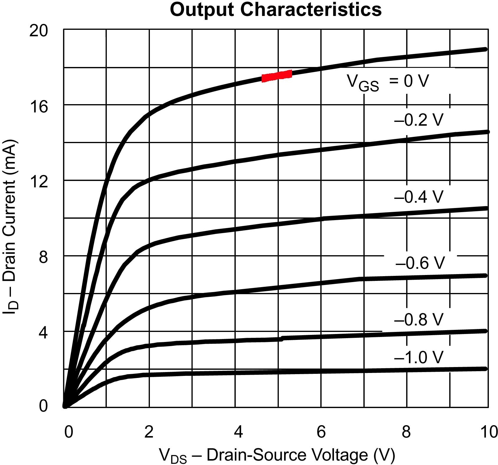
All these values depend on the others, and the angles, distances and curvature of the plotted lines tells us things about how the transistor behaves. The distance between the plots tell us the gain of the device at that spot, the angles of the lines tells us how the Vds affects the gain, and the curvature and uneven spacing of the lines show us the non-linear distortion of the device in any given area.
As the Ids increases, the spacing between the curves increases, reflecting increased gain of the Jfet, and this causes a non-linearity which gives us 2nd harmonic distortion with a "positive phase". As the Vds decreases, the slope of each line shows a gain decrease which gives us 2nd harmonic but this time with "negative phase". More on the phase later...
There is a "sweet spot" where these two effects cancel, and the 2nd harmonic disappears, leaving traces of 3rd and other harmonics.
These curves are our guide to selecting an operating region where we can get the 2nd harmonic distortion we might want. We can set the operating voltages and current at a particular point, and the amplified signal will reflect a balance between these two effects.
In the graphic above, I have marked an area of interest in red. For this particular Jfet, the region in or near the red zone gives us some 2nd harmonic, and by operating the Jfet in Common Source Mode at the Idss current and without degeneration we can adjust the harmonic content merely by varying the supply voltage a bit.
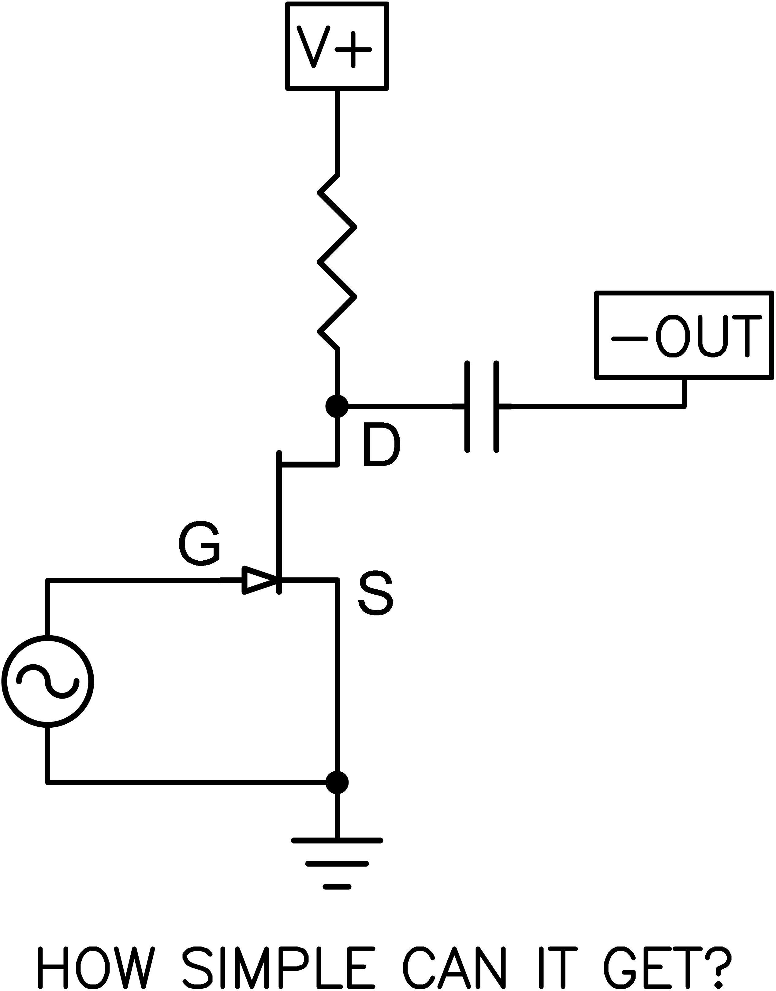
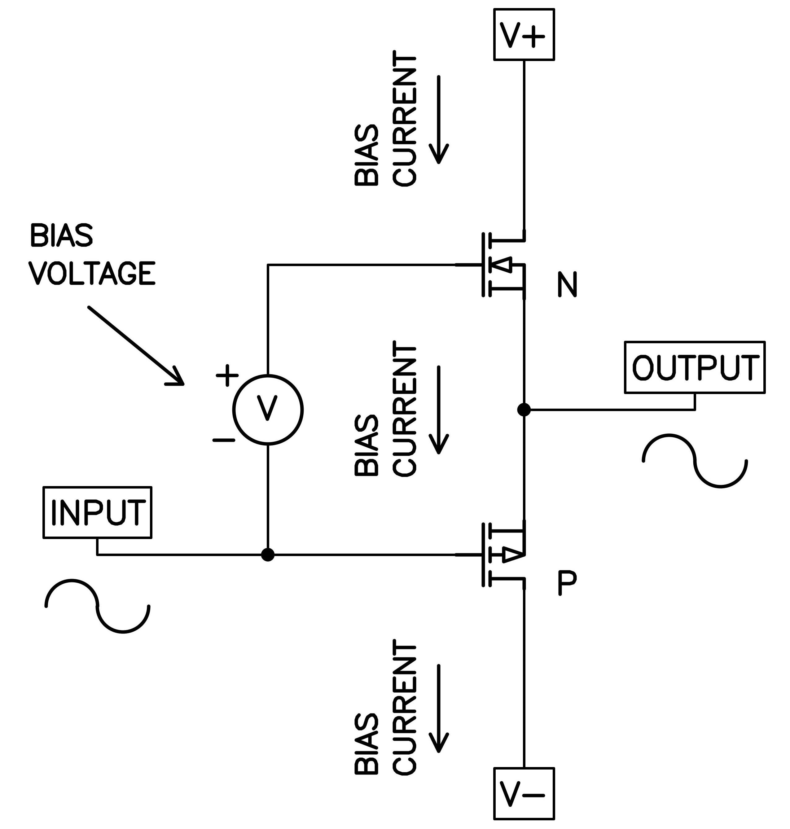
Above is what the basic circuit looks like. The Source pin is grounded and the Gate is attached to something that provides audio signal. The output Drain pin is fed current through a resistor going to the supply voltage and the output is taken from the Drain through a capacitor which blocks the DC voltage of the Drain, which is about 5 volts DC.
When I say Common Source Mode, I mean that the signal goes in the Gate and comes out amplified at the Drain. The Source is grounded. This mode gives both voltage and current gain, and inverts the absolute phase of the signal. And when I say degeneration, I am referring to resistance between the Source pin and Ground, which we don't have here.
Having previously designed with SIT (VFET) single-ended amplifiers and also the Korg Nutubes, I have worked up some performance targets which deliver an effect that is usually well-liked. This is described as having negative phase 2nd harmonic at approximately 1% of the amplitude of the original signal.
The Importance of Phase
There are technical people who don't think phase in audio signal is important. I think that it does make a difference, but it is easy enough to assure that your audio chain retains absolute phase. There is poor assurance that the original material was recorded with correct absolute phase, but that's another issue.
We have here a circuit which inverts the absolute phase, but we can correct for that with an additional reversal either before or after the circuit. There is a difference on the choice of before or after, as we will see later.
Here is an oscilloscope shot of a sine wave (representing audio signal) in red, and also a waveform showing the greatly magnified 2nd harmonic distortion which accompanies it in blue.
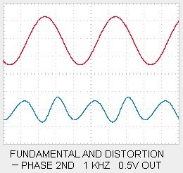
The red fundamental goes up and down at a 1kHz rate, and we see that the blue wave goes up and down as well at twice the frequency, but aligned with the red wave in a particular way—the blue goes down when the red goes up and the blue also goes down when the red goes down. I refer to this as negative phase 2nd harmonic. Positive phase 2nd harmonic is the opposite:
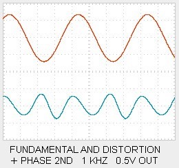
With positive phase 2nd harmonic, the blue goes up when the red is either up or down.
It's important to note that this circuit actually generates a positive phase 2nd harmonic, but after you invert the output (to get absolute phase correct) you will find that it is now a negative phase 2nd harmonic. I know this might be confusing—I have occasionally awakened in the middle of the night and thought "That can't be right." But it is, and if you turn the above pictures upside down you should see it. If not, just invert the phase at the speakers anyway. If you invert the phase of the signal before the circuit, then it will keep the positive 2nd.
So why is the phase important? Well, it's a subtle thing. I don't suppose everyone can hear it, and fewer particularly care, but from listening tests we learn that there is a tendency to interpret negative phase 2nd as giving a deeper soundstage and improved localization than otherwise. Positive phase seems to put the instruments and vocals closer and a little more in-your-face with enhanced detail.
Your results may vary, but when I first explored this with the SIT-1 amplifier at First Watt, I had a knob on the front of the amplifier which varied the amount and phase of the 2nd harmonic. It was easy enough to lend the amplifiers to listeners who didn't know what the knob did and gather their comments. Roughly speaking, they tended to prefer about 1% negative phase 2nd harmonic, so it became my standard setting for that knob.
Of course we understand that all this is an illusion, like most of the rest of audio perception - you are welcome to take my remarks as entertainment.
The Circuit
Here is the circuit that I made for you to play with. Note that only one channel is shown, but that the power supply regulator serves both channels.
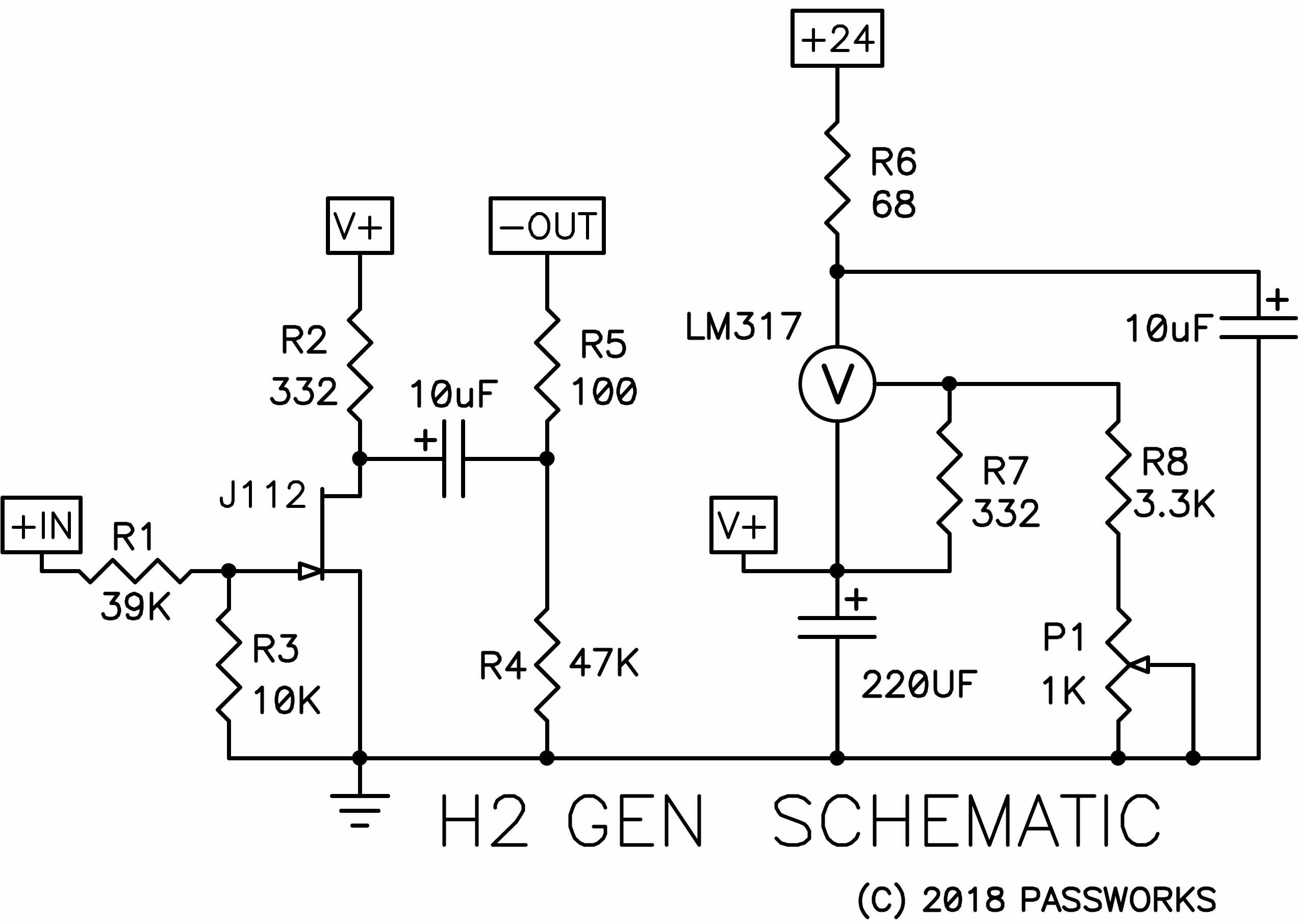
The J112 Jfet has been chosen as a suitably cheap choice and carefully matched out of a population with a 2 to 2.5V pinch-off voltage and an Idss of about 30-40 mA. In this circuit this Jfet has a voltage gain of about 14 dB, and could easily serve as a preamp with a volume control and such. Here I have chosen to use it as a unity gain line stage, so I used R1 and R3 as an input voltage divider. If you reverse the values of R1 and R3, you will have lots of gain, more than 10 dB, even more if you change the 10K resistor to 1K.
R2 is the Drain load for the Jfet, setting the intrinsic gain and voltage/current conditions and also providing most of the output impedance of the circuit, which is about 400 ohms after the 100 ohm resistor R5. R4 is just there to drain off the DC and make sure the output DC eventually gets down to zero on turn-on and turn-off.
Speaking of that, this circuit has a substantial turn-on and turn-off thump, so you want it powered up before you turn on the power amplifier, and you also want to leave it running.
The power supply is a regulated 24V DC wall wart. You can use 19V DC instead, but then you would also want to set R6 at much less value, say 10 ohms, as it drops a little more than 4V in the current circuit, and does a little RC filtering in addition to taking some dissipation off the LM317 regulator chip.
Yes, the regulator is a "crummy" LM317. A bit noisy, but I took most of that out with a 220 uF capacitor. It has to be adjusted to a specific voltage for the matched Jfets to get the target distortion curves. If you have a distortion analyzer, you're all set, but if not, any kits will come with a calibrated value for each Jfet.
Here are some performance curves on the circuit:
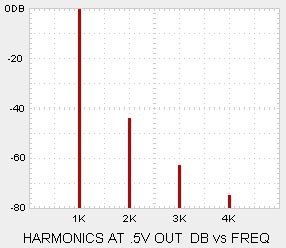
Above is what the spectrum looks like at 0.5V output, where you can see the relative amounts of 2nd, 3rd and 4th harmonics. We note that the 3rd is down about 18dB from the 2nd, and the 4th is lower yet. This is approximate, and varies a bit between Jfet parts.
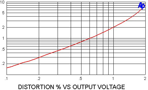
Here is the distortion vs the output voltage. You can see that this circuit is usable to about 2 volts, but it is desirable to keep it in the region below a volt or so. For an amplifier having 26dB of gain, this corresponds to 100 watt peaks at the loudspeaker—plenty for me!
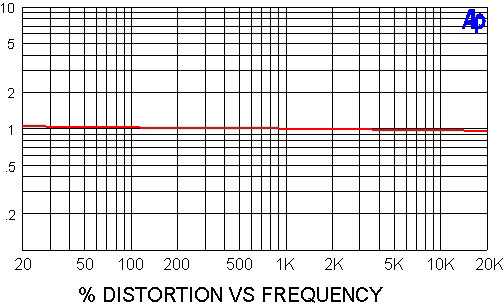
And below is the distortion vs frequency, not a surprise for a no-feedback circuit:
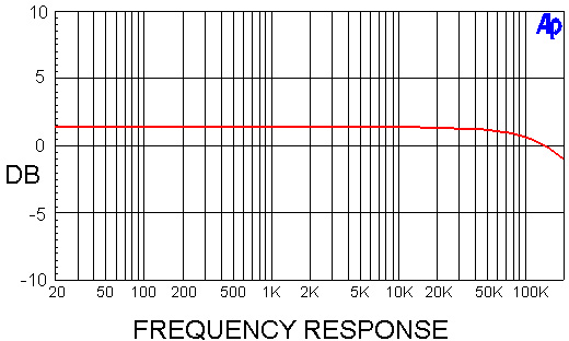
Lastly, here is the frequency response, down 3 dB at 200 Khz.
Additional Notes
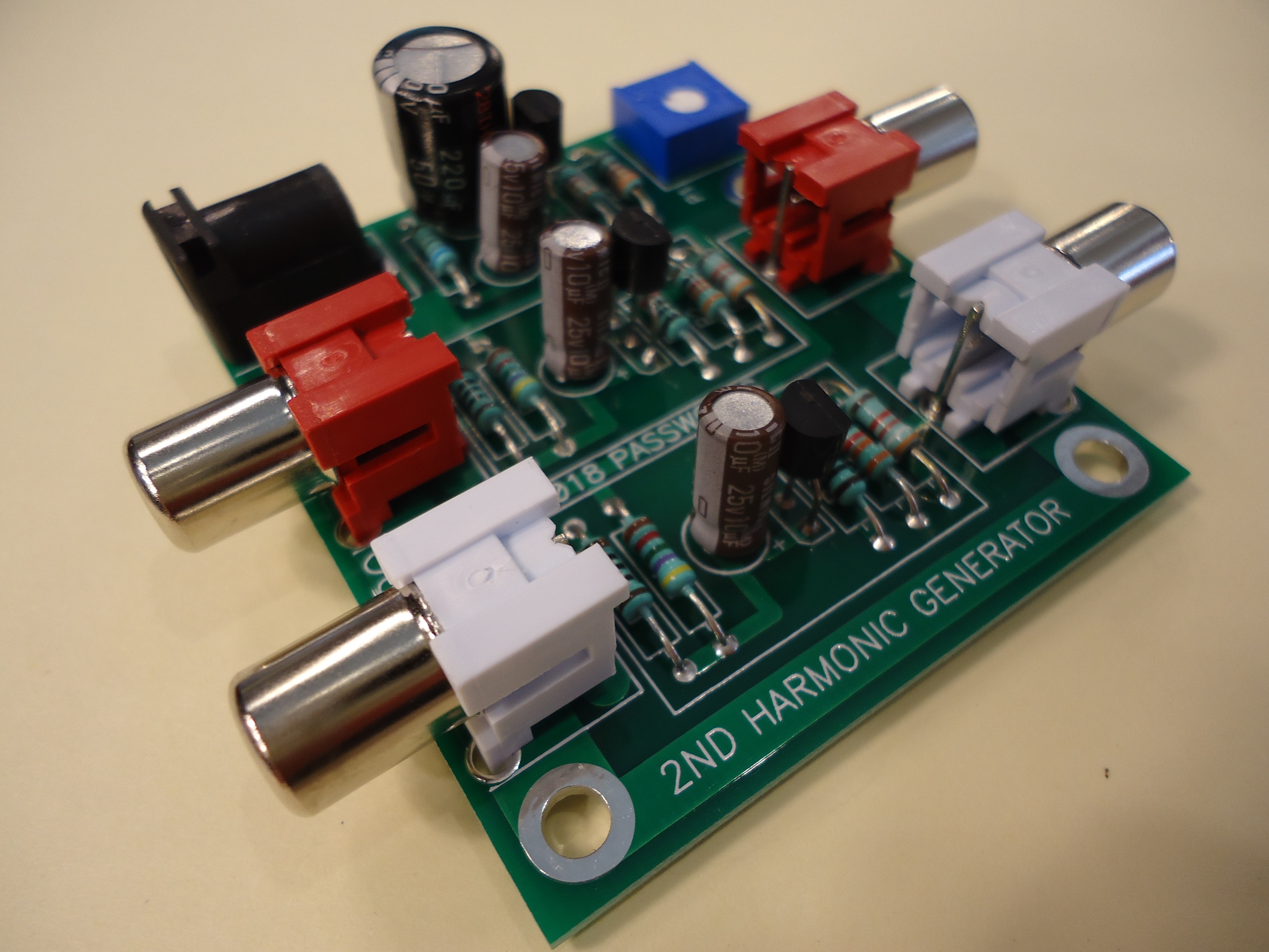
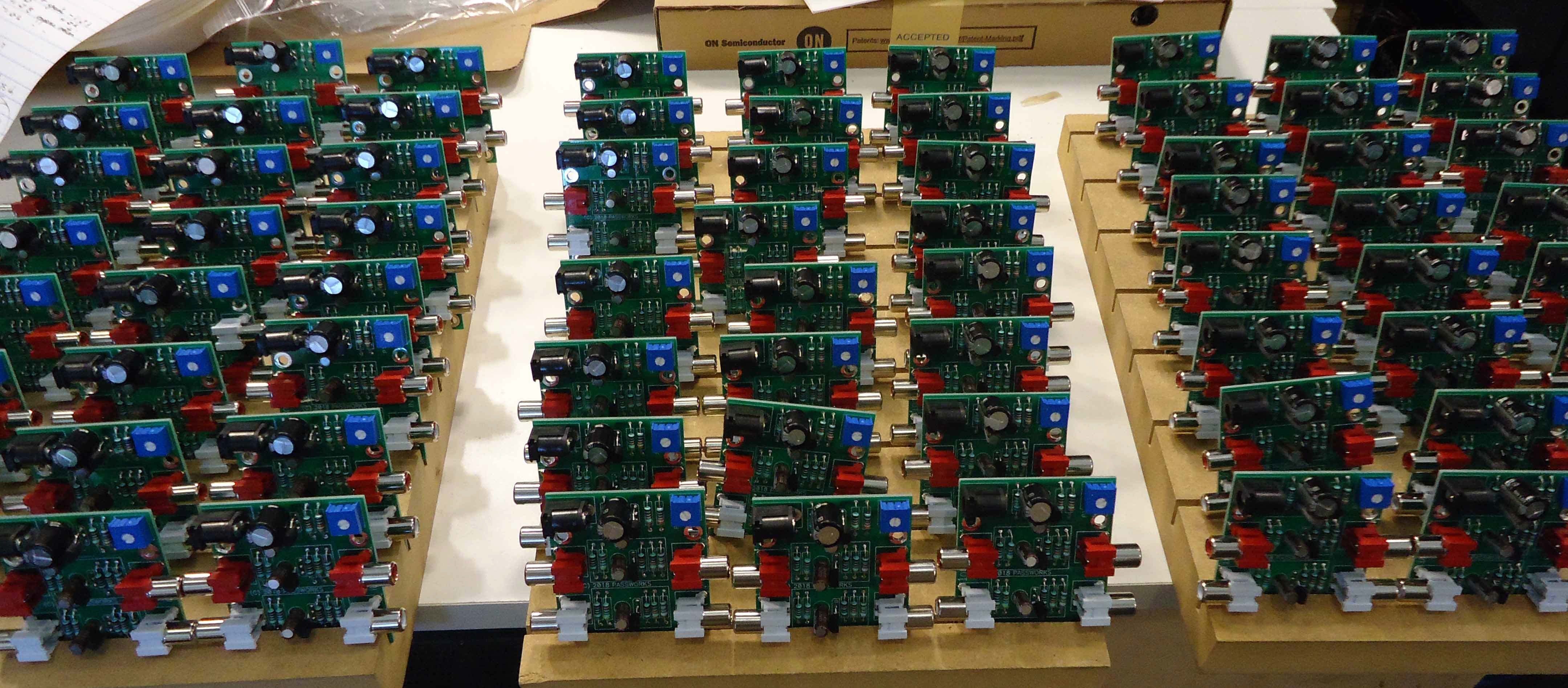
I made up a small batch of of these H2 generators for distribution at 2018 Burning Amp Festival. It's a little circuit board example, stuffed and calibrated. The calibration for the distortion curve is based on the regulated voltage from the LM317, and that voltage is noted in ink underneath the potentiometer. You can play with this value by turning the pot, and return to the calibrated value by setting the voltage to the original value.
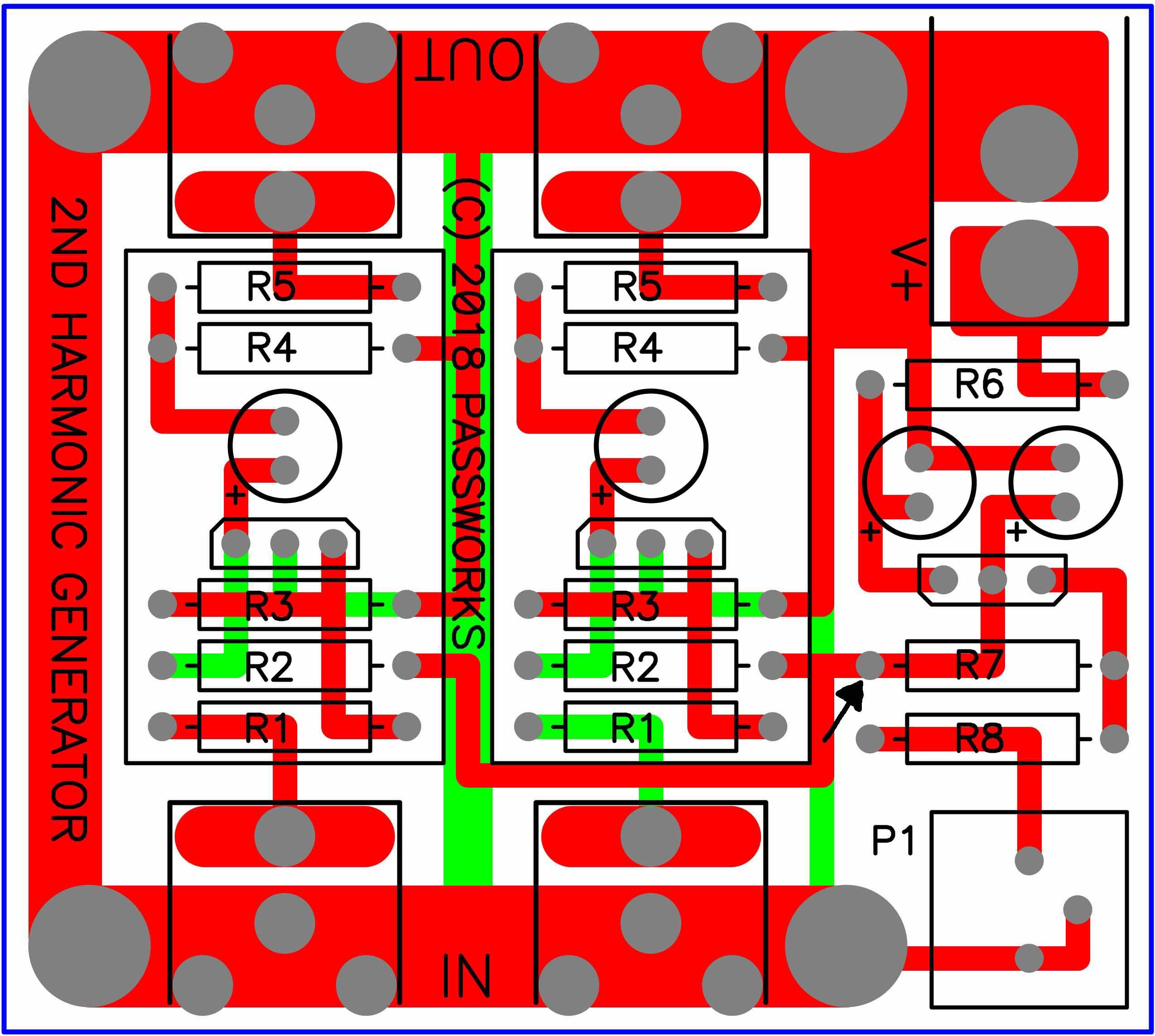
Here is the circuit board with traces shown and component numbers. You will see an arrow at R7 where you can measure the DC voltage of the regulator relative to ground, which is found at the four large mounting holes.
You will find that the practical adjustment range is about +/- 0.3V of the original value. As you turn the pot clockwise, the regulated voltage goes down and the distortion goes up. If you go counter-clockwise, the regulated voltage goes up and the distortion goes down.
As mentioned before, you can use a 19V regulated supply, but the value of R6 should be reduced to 10 ohms or so.
The board is intended to be placed in a shielded chassis for low noise, but you can run it in the open if you are cautious about not setting it on a conductive surface (duh) and keep in mind that 24V is still considered a bit hazardous. In no case do we take it into the bathtub, etc. Remember that as a DIYer, you are responsible and are required to use common sense.
Also as a DIYer you are likely to want to screw around with the circuit and customize it in various ways.
At BAF I will also have some unstuffed boards for the more adventurous. I recommend that if you embark on building up your own that you have some test equipment to evaluate the performance—it is very difficult and tedious to do by ear, believe me.
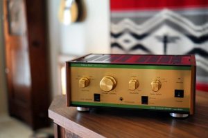
As a teaser, here is a picture of the stuffed board, complete with connectors and such.
Final Comments
This circuit is fun to play with, but inevitably some people will it seriously, especially if they like what they hear. There will be plenty of people who won't care for the effect, and that's perfectly OK. I'm giving these away, so no whining.
A few comments:
- Remember to reverse the phase on the speaker connections to the amplifier. You don't have to though—it would also give you a chance to hear the positive phase 2nd
- There is an optimal level for this circuit, at outputs of about 1 volt or less, otherwise the distortion will get actually excessive, assuming that it isn't You'll know when that is, but figure on amplifiers with 20+ dB of gain and normal listening levels.
- This circuit is designed around regular solid state power amps, the kind most people have. I personally think that this is a trick best played only once in the audio chain, so if you already have a SET amp or some other component with lots of 2nd harmonic, you want to temper your expectations when used with this also. Or maybe you want to hear what your SET sound like with the 2nd harmonic .....
- It tends to sound best when presented by fairly simple audio material at levels your neighbors don't complain about. Massive orchestras and large choral performances at high levels can get congested when the 2nd harmonic is
- It's hard to break this circuit, but keep in mind that it has a big thump at turn-on and turn-off.
- And this is what you'll be missing if you don't come to BAF 2018 –
(c) 2018 Nelson Pass
All images courtesy of Nelson Pass, except as noted.