|
You are reading the older HTML site
Positive Feedback ISSUE 66
Mountains and Fog: the Sound of
Digital Converters, Part Two
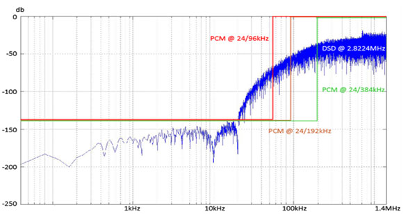
Modern delta-sigma converters rely on a combination of internal high-speed upsampling and noise-shaping algorithms (digital feedback wrapped around the switch array) to attain their performance. Without dither + noise-shaping algorithms, you only get 12-bits to 14-bits of resolution, and we'd all still be using ladder converters. Single-bit converters (and the SACD/DSD system) rely on dither and noise-shaping even more. Without noise shaping, SACD/DSD at 64fs (2.8224MHz) would only have 6-bits, or 36dB, of dynamic range, about the same as a not-very-good telephone connection. Andreas Koch, of Sonoma and Playback Designs, who probably knows DSD better than anyone in the world, has a white paper here: http://www.playbackdesigns.com/start-here/dsd-explained-by-andreas-koch/
Note the DSD noise level at 15kHz; an astounding -144dB, better than the performance of the ESS 9018 in 24/192 PCM mode. How do we get from -36dB to -144dB? Far above the noise-shaping region, around 700kHz, we see the expected -36dB figure, but in the 20Hz to 15kHz audio range, performance exceeds any DAC chip in the world (physical converters you can buy are always worse by 2- to 3-bits than ideal system performance). The wall-of-noise rises fast, going from -144dB at 15kHz to -96dB at 20kHz. That's 48dB/octave, implying an 8th-order noise shaper (each order reduces noise at a 6dB/octave rate). I understand that noise-shapers are used at the encode and decode end, but what of the system as a whole? There's no way to wrap feedback around a recording made in 2001 and played back in 2013, unless we invent time travel. Looking at the bitstream coming out of the encode ADC/noise-shaper, and the bitstream going into the decode DAC/noise-shaper, I see a string of DSD samples at the 64fs rate. If a single Red Book sample is 22.7 microseconds, each of these little DSD samples is 355 nanoseconds. Like the bigger Red Book samples, they cannot be altered in time or amplitude; they are discrete samples, and are either ones or zeroes. For the sake of this example, all the extra error-correction data needed for SACD or computer-disk recording will be ignored, since it doesn't affect the operation of the underlying ADC/DAC bitstream. As in the previous example, full positive modulation is (ignore the extra spaces added for readability): … 1111 1111 … Full negative modulation is: … 0000 0000 …. Zero analog signal is either: … 0101 0101 … or … 1010 1010 … Which simply represents half-modulation. After level-shifting, it comes out to zero analog signal. I have a question: what is the smallest signal this system can represent at 3.675kHz, and what would it look like in the DSD bitstream coming out of the ADC? I've picked 3.675kHz since it is close to the peak sensitivity of the ear, and a convenient divisor of 44.1kHz. The smallest possible 3.675kHz signal would be nothing more than a single "one" that replaces a zero in the following string: … 0101 0111 0101 0101 … All the rest of the string is the usual tedious … 0101 0101 … pattern mentioned above. Except for that lone "one", all the rest come out as analog zero. How often does the rogue "one" appear? That's easy: 3,675 times a second. (Yes, I know that creates a small DC offset, but let's ignore that for now. Besides, practical DACs don't usually pass DC anyway, to protect the power amplifier in case the recording has an accidental DC offset.) S/N ratio? Again, easy. The DSD samples are clicking by at a rate of 2.8224MHz, and we're interested in our one little guy at its 3.675kHz rate. Our "one" appears once every 768 DSD samples. The smallest possible modulation at 3.675kHz is one part in 768, or 9.5-bits, or -57dB below full-scale modulation. But there's a problem with this simple little example. When you convert the time data of this example to frequency spectra, it doesn't look like Andreas' graph at all. There's no noise: just a -57dB spike at 3.675kHz, and full modulation at 1.4MHz. That's not what DSD actually looks like; instead of a single spike at 1.4MHz, it's filled with noise—which is intentionally added as dither at the encode end. What would Andreas' original graph look like translated into time? Like this: … 0011101100011100110011110011100011001111000 … There are fine-grained clumps of noise only a few samples long, but averaging to analog zero over durations longer than 67 microseconds (the inverse of 15kHz). All it would take to encode 3.675kHz is an ever so slightly larger clump of noise at a 3.675kHz rate. It would be so tiny and well-mixed with random noise, you'd never see it in the time domain data. Hmm… clumps of noise, averaging to a medium value. This is exactly what you'd see if you made a one-line linear film scan of a 35mm negative exposed to medium gray. The exposed clumps of silver halide are black; there are no gray clumps, and the film base is clear. In other words, ones and zeros. The brightness value of an area is an inverse function of the size of the grains; bigger grains are darker and take up more space on the film, and smaller grains let through more light. Unlike digital, though, the film grain comes in all different sizes, with no quantization of size. But like DSD digital, the distribution is random; the eye will easily discern any pattern in the film grain, and the ear will detect spectral peaks in the noise. If you made a high-resolution linear scan of a variable-density optical soundtrack, this pattern of small clumps-of-grain is exactly what you'd see. I wonder if that's where Sony got the idea for DSD modulation in the first place. In the absence of noise-shaping, the resolution of DSD is a function of frequency; the higher you go, the less there is. At what frequency do we get 16-bit resolution? Well, 16-bits represents 65,536 possible levels; let's divide 2.8MHz by 65,536, and we get 43Hz. With every octave above 43Hz, the resolution drops by another bit, topping out at 1 bit 2.8MHz. But… that's before noise-shaping is applied, which pushes the noise above the audio band. The dramatic difference between unshaped and shaped noise in the DSD system is what makes it possible. As usual, there's no free lunch in audio: designing stable noise-shaping systems is very difficult, and in studio applications, there is a limit to how many times noise-shaping can be applied. There's a fascinating discussion by Bruno Putzey of Philips Digital System Labs at the following link: http://forums.stevehoffman.tv/threads/sacd-fundamentally-flawed.26075/page-3 Bruno mentions that too many generations of DSD can result in so much HF noise that clipping starts to happen, which destroys the DSD signal. The professional solution is DSD-Wide, which is 2.8MHz/8-bit, which increases the dynamic range and removes the need for consumer-type noise-shaping. Since it is nearly impossible to level-adjust, equalize, compress, or add reverb to a DSD signal, professionals convert DSD to 352.8/24 DXD (PCM), process the signal in the usual PCM way, and convert back to DSD. About the only time a DSD signal remains in DSD format is when a 2-track analog mastertape is converted to DSD, and the DSD is left intact all the way through to the consumer. Comparing DSD to PCM, what stands out is the Nyquist frequency (the highest frequency that can be modulated) is a remarkable 1.4MHz, in video territory. The resolution is only 6dB, but it will indeed carry modulation. The Nyquist frequencies for PCM are much lower: 22.05kHz for Red Book CD's, 48kHz for 96/24, 96kHz for 192/24, and 176.4kHz for 352.8/24 DXD. It's clear DSD is optimized for time response, with near-video impulse response, and does not require the brickwall filters of the slower PCM formats. It certainly looks impressive on a scope, which the DSD proponents use to promote the system. But… what you see on a scope doesn't correspond all that well to how we hear. For one thing, it's nearly impossible to see less than 2% distortion on a scope, and 2% distortion is audible to nearly any listener. In effect, the visual dynamic range of a scope display is about 6-bits, which isn't even good enough for mobile-phone quality. Scopes are all about impulse response. Good-looking square waves require response 10x higher than the fundamental signal; so a recognizable 10kHz square wave needs reasonably flat response out to 100kHz. Does this happen in the real world, with microphones that are used for music recording? Sure, B&K and Aco Pacific will gladly sell you calibrated ¼" microphones that are flat to 80kHz, but do pros use them? No. Professionals use large-diaphragm condenser microphones and ribbon mikes with built-in transformers. There is response beyond 20kHz, but it's pretty rough, and is pretty much all gone by 50kHz. It's the same story for tweeters in loudspeakers. True, there are tweeters with extended response… 40kHz isn't unusual for ribbons… but the response starts to get ragged above 30kHz. The only tweeters I know of that are flat to 100kHz are open-air (not horn-loaded) ionic tweeters, and these have serious issues with ozone generation and sound levels above 90dB. The best ribbons make it to 40kHz, and dome tweeters and compression drivers struggle to make it much beyond 20 to 25kHz. In terms of overall transient response from microphone to loudspeaker, we have to remember the limitations of the transducers on each end. In practice, 50kHz is about the upper limit for the highest-quality recording and playback systems, with 20 to 50kHz present but not very flat. You could make a good case that 176.4/24 PCM upsampled with high-quality filters to 352.8/24 or 705.6/24 exceeds the time-domain performance of just about any microphone and loudspeaker, with 88.2/24 PCM upsampled to 352.8/24 or 705.6/24 a close second. The Nyquist frequency of 352.8/24 DXD/PCM is far above the upper bound of any microphone or loudspeaker, now or contemplated in the future, so Gibbs ringing around the corner frequency will never be stimulated with actual musical sources. The most likely source of coloration is on the DSD end; when DSD is converted to (very) high-resolution DXD/PCM, noise-shaping algorithms are required in the conversion process. Referring back to Bruno Putzey's comments, there is a limit to how many times noise-shaping can be applied to an audio signal before problems start happening. DSD-Wide (2.8MHz/8-bit) is interesting professional format; unlike DSD-Narrow, it doesn't require noise-shaping, thanks to abundant dynamic range. To the extent that any DSD system has coloration, it can be laid at the door of the noise-shaping algorithms of the A/D and D/A converters. If there is any DSD system that has the "character" of a ladder converter (which do not use noise-shaping), DSD-Wide would be it. Let's step back a bit and look at digital converters. There are three main types: Ladder or R-2R converters (Philips TDA154x series and the Burr-Brown PCM 63, 1702, and 1704), which have dither applied to the encoded original, but do not employ noise-shaping in any form. Each sample, whether it is 22.7, 11.38, or 5.2 microseconds, is decoded at full resolution, with a switched resistor for every bit-level in the original datastream. Ladder or R-2R converters decode one sample at a time; there is no feedback, memory, or look-ahead. With no feedback, and one-step conversion, these devices are sometimes called "flash" converters. Oversampling ratios vary from unity (NOS, or non-oversampling), 4 times, or occasionally 8 times. Oversampling algorithms vary in sonic quality—some are good, some are not, but all benefit from appropriate dither spectra added to the LSB of the data stream; the appropriate dither level is about ½ of the LSB of the intended converter. (For example, a true 16-bit converter like the Philips TDA 154x series would have dither at ½ of the 16th-bit level, true 20-bit converters like the Burr-Brown PCM-63 and PCM-1702 would have dither at the ½ of the 20th-bit level, and the Burr-Brown PCM-1704 would have dither at the ½ of the 24th-bit level.) The ideal noise spectra is a "triangular" spectra centered on the Nyquist frequency of the physical converter—in other words, if the converter is running at 352.8MHz, the center of the dither-noise spectra should be 176.4kHz. Delta-sigma converters have grown steadily for the last fifteen years, and now have nearly the entire market. They are the technology that supplanted both single-bit and ladder converters. The number of internal-bits may be 5 or 6, and the converter operates at very high oversampling ratios; 256fs or higher. Dither is typically applied at the level of the LSB of the physical converter—in other words, at the 5th or 6th-bit level – and noise-shaping feedback is applied to move the dither-noise above the audio band. Noise-shaping is digital feedback wrapped around the converter array, linearizing it from the inherent 5 or 6-bit resolution to 24-bits or better. Noise-shaping requires the combination of high-speed oversampling, LSB dither, and digital feedback to work its linearization magic. Noise-shaping generates substantial amounts of ultrasonic noise, which is a challenge for the analog section of the DAC. There are stability problems (resulting in idle tones, jumps in noise level, etc.) that arise from noise-shaping techniques, and different converter vendors have taken different approaches to resolving these problems. I suspect that the most advanced delta-sigma converters use signal-dependent dither (decreasing it at the highest levels, to prevent overload, and increasing it at lower levels, to improve stability of the noise-shaping system) as well as adaptive noise-shaping, that detects when instabilities are encountered and alters the internal feedback coefficients so the instabilities are quickly removed. (Feedback with monitoring, as it were.) Single-bit converters, which preceded delta-sigma converters. These were originally designed by Sony and Panasonic for portable, battery-powered applications, and gradually moved into mainstream applications. They require the highest levels of dither of any type, as well as the highest level of noise-shaping, since there is only one switch, with two possible levels—OFF and ON. The LSB and MSB (most significant bit) are one and the same. If single-bit converters operated at GHz speeds, they would not need noise-shaping, but the converters we have today operate at speeds similar to delta-sigma converters. Without dither combined with noise-shaping, resolution would be in the 6-bit range; with dither and high-order noise-shaping, noise can be reduced to a remarkable -145dB—in the audio range. Above 15kHz, noise rises very rapidly, corresponding to the order of the noise-shaping feedback system. The "noise" level at 1MHz is around 2% of full modulation; most opamps are not linear at frequencies that far out of the audio band (1MHz is the middle of the AM-radio band), and steps need to be taken to isolate opamps, or feedback-based analog circuits, from the RF noise. The design of the noise-shaping algorithm, in a real sense, is the sound of the delta-sigma and single-bit converter, since the converter would sound (and measure) far worse without it. Although DSD purists throw up their hands in horror at "hybrid" PCM/DSD systems, I'm not too sure they're all that different from each other, at least in terms of what's going on in the converter. Both types of converter have "native" resolutions in the 5 to 6-bit range, and use dither-noise and noise-shaping algorithms to extend linearity and dynamic range to 24-bits or more. Single-bit converters are delta-sigma converters on steroids: the level of dither is considerably higher, and the order of noise-shaping is greater. This puts a steeper burden on the noise-shaping design team to avoid idle tones, program-driven changes in noise level, and other noise-shaping artifacts (which do not show up in steady-state measurements). See the ESS presentation at: http://www.youtube.com/watch?v=1CkyrDIGzOE This is a once-over-lightly on the problems of noise-shaping; it only touches the surface of a very complex area of digital design. The most important AES papers are behind the AES pay-wall, and you need a pretty good understanding of mathematics to follow what they're talking about. This is also an area of vendor secrecy: the key differences between different delta-sigma converters are proprietary, and probably only known to the design team that designed the chip. If you sign a non-disclosure agreement (NDA) the vendor will tell you more than the bare-bones spec sheet and application notes, but that's not the whole story. Remember, it's the noise-shaping algorithm that gives a delta-sigma converter it's sound, and that's the part they're not telling you. I suspect many delta-sigma converters with a DSD input might not be switching all of the switches from 0000 to 1111 at the same time, which would emulate a Sony-type, late-Eighties single-bit converter. It might sound a little weird, but a simpler method would be to internally translate DSD into short word-length PCM patterns, taking advantage of the dynamic range of the 5 to 6 switches (partial analog, as it were). That relaxes the severe noise-shaping demands of DSD back to the realm of "conventional" delta-sigma converters. It's the requirement to linearize a single on-off switch that causes all the trouble; it takes much less noise-shaping to linearize 0.006% distortion (6-bits at 256fs) than 2% distortion (1-bit at 64fs). Looking at DSD in this light, I can see why 64fs and 128fs DSD sound as different as they do. The increase in speed shifts the noise corner from 15kHz to 30kHz, and one more bit of inherent resolution is obtained (which is a big deal). Put another way, the noise-shaper doesn't have to work quite as hard, which relaxes the stability and design requirements of the digital feedback networks. I'm also guessing that commercially available DSD decoders take advantage of higher-speed DSD (128fs and 256fs) and alter the noise-shaping algorithm, possibly decreasing the order of the noise-shaping, which will alter the character of the sound (since noise-shaping, to a large degree, is the sound of delta-sigma and DSD decoders). Analog Requirements As mentioned above, the 1MHz (and higher) spectra of the three main types of converter are fundamentally different. Ladder or R-2R converters generate a comb spectra that follows the digital input fed into it; for example, a ladder converter fed a digital 20kHz tone will generate a "comb spectra" with narrow spikes going all the way out to 20MHz; the enormous number of harmonics is the frequency-domain result of the extremely fast rise-times of the stair-step waves coming out of the converter. If you lower the level of the digital input going into the converter, the comb spectra will also decrease, all the way down into the noise. In other words, the RF spectra tracks the level of the input signal. Not only that, the density of the RF spectra mirrors that of the input signal; a dense input spectra will produce a dense RF spectra. If the ladder converter has an internal opamp producing a voltage output, the internal opamp will almost certainly slew, which limits the output above 50 to 100kHz. Keep in mind that slewing is not at all the same as low-pass filtering with passive components; the slewing results in inaccurate reconstruction of the digital samples, with the error (distortion) rapidly increasing at high frequencies. Although an internal opamp relaxes HF requirements for the following analog stages, the slewing cannot be removed—and is hidden from sight, unless you look very closely at the rise-times of the output. Slewing is also level-dependent, so quieter signals will have less slewing. If a converter, or an entire DAC, is clean at lower levels, but gets more congested at higher levels, slewing in the analog stages is the first place to look. Delta-sigma converters are available in current and voltage-mode models; the voltage-mode models typically have internal opamps, which most likely exhibit slewing. If you see an extended comb spectra extending beyond 1MHz, the converter either has a very fast internal opamp (this is unlikely, since these devices are expensive) or uses a current-mode output. One key difference with delta-sigma converters is the presence of ultrasonic noise in the absence of digital input, although some vendors "cheat" by shutting off the converter when digital silence is detected. The noise is the result of the noise-shaping techniques mentioned earlier; internal dither is applied at the 5th or 6th-bit level (whatever the physical LSB of the converter happens to be), and noise-shaping shifts it out of the audio range into the 1MHz and above range. Since the RF looks kind of ugly, and is a hassle for the analog designer to contend with, voltage-mode converters that conveniently remove all the ultrasonic crud are popular. Add a buffer opamp to one of these, and you're done. Manufacturers of higher-quality converters assume the analog designer is competent enough to read an application note and design a current-to-voltage converter, followed by a low-pass filter, with opamps like the antique 5532/5534 and the more modern 797 popular choices. Although this is not ideal, it is the most common approach, and provides the best-looking measurements. The amount of always-on ultrasonic content depends on the degree of noise-shaping; I'm guessing here, but it will probably be anywhere from -40dB to -60dB at 1MHz. The always-on ultrasonic noise is in addition to the signal-dependent comb spectra mentioned earlier, which goes up and down with signal level. Single-bit converters are similar, with the difference that the steady-state, always-on ultrasonic noise is at a higher level, due to the higher level of dither-noise and the higher order of the noise-shaping system (which shifts the dither-noise upwards). At 1MHz the noise level shown in Andreas' graph is -36dB from full modulation, which is consistent with a 6-bit (1-bit at 64fs) system. This is with zero digital input; I have no idea what kind of out-of-band spectra DSD generates when it is fed a signal, but it's possible it's not the kind of comb spectra that PCM generates. And this is where the biggest sonic difference might be: DSD, and to a lesser degree delta-sigma PCM, have a different ultrasonic spectra than ladder-converter PCM. All three classes of converter generate ultrasonic spectra, but are quite different in content. Ladder converters create narrow spectral lines that track program content, while DSD creates broadband noise in the 1MHz region. The most widely used opamps, like the 5532/5534 and 797, have very poor linearity in the MHz region. Audio opamps are not video amplifiers; the feedback is almost gone at these frequencies, Class AB switching is much more prominent, and slewing (intervals of 100% distortion; input and output no longer correlate) can easily occur. How easily? Well, to reproduce that 20MHz comb spectra requires a device with a slew rate of 1000V/uSec. The 5532/5534 has a slew rate of 13V/uSec, the 797 a slew rate of 20V/uSec, and many other audiophile favorites are no higher than 50V/uSec. If the designer chooses to use active current-to-voltage conversion with an opamp (a transimpedance amplifier), the opamp will be exposed to transitions that are 1000V/uSec or faster. If the designer chooses to use an active lowpass filter, such as the popular Sallen & Key circuit, the active filter has increased distortion at the corner frequency, thanks to positive feedback. In other words, the filter gets in trouble at the same frequencies it is meant to remove! Unfortunately, the most popular analog architecture in high-end DACs is just what I've described; active current-to-voltage converters using low-speed opamps (selected for ultra-low noise and very low THD at audio frequencies), followed by the active filtering using a similar type of opamp. The MHz frequencies that are causing all of the trouble don't disappear until the output of the active lowpass filter. What happens when the MHz output of the converter crossmodulates with audio at much lower frequencies? Distortion – folded down to the audio band. Opamp distortion from 1MHz to 10MHz range can be expected to fall in the 0.1% to 3% range, as a result of 60dB less feedback (compared to 1kHz). See the following paper by Fiori and Crovetti, published in the IEEE Transactions on Circuits and Systems: http://www.uemc.polito.it/papers/opampsusc_01.pdf In the interest of power efficiency, opamps usually have Class AB output stages; this is not a problem at audio frequencies, thanks to very high feedback ratios, but at a MHz or more, with feedback mostly gone, a Class AB opamp will have poorly controlled Class AB transitions. A device that is well-behaved at 1kHz is not as well-behaved when operated at a frequency a thousand to ten thousand times higher. If the MHz content from the converter is white noise, the baseband audio spectra will be thickened by close-in IM distortion. Narrow spectral lines will have phase noise added, making the spectrum denser. This might not sound too bad; what made the Yamaha DX7 synthesizer "The Sound of the Eighties" was FM modulation of the synthesizer tones. FM modulation, of the right kind, adds a thickness and density to the sound. Thin-sounding musical sources might actually sound a bit more "filled-out", but full symphonic or choral music could turn into a roar of distortion. The narrow spectral lines of the ladder/R-2R converters would sound quite different; there would be non-harmonically related IM tones moving through the audio band; the nature of these tones would depend on just how badly the opamps handled the MHz region. As long as low-speed analog circuits are exposed to RF frequencies, the audio band will be filled with distortion artifacts that have an extremely complex relation to the input signal. Once slewing and cross-modulation from RF interference happens, no amount of clean-up after the fact can correct it. The character of the distortion artifacts will be different for ladder converters, delta-sigma converters, and DSD converters. Which takes us to the next section—how do we measure what's coming out to the converter? Measuring Ultrasonic Content How much ultrasonic content does a converter generate when fed a 20kHz full-modulation tone? The Burr-Brown PCM-63 ladder converter generates a "comb spectra" that is flat out to 20MHz and declines into the noise floor at 50MHz. (It's real. I saw this for myself on the HP spectrum analyzer screen.) How is this measured accurately? The ultrasonic content from the RCA or XLR of DAC audio component is not of interest; you want to see what is coming directly from the converter chip itself. The circuit board trace that goes to the current-output pin of the DAC chip can be temporarily soldered to the center conductor of a 50-ohm coax cable that goes directly to an RF spectrum analyzer (the cable shield is soldered to the trace going to the analog ground of the DAC chip). The analyzer needs to have 100MHz bandwidth, and an on-screen dynamic range of at least 80dB, preferably more. The Philips TDA 154x series of DACs, and the TI/Burr-Brown PCM-63, 1702, and 1704 DACs work correctly with a 50-ohm termination, which is provided by the RF spectrum analyzer. Some analyzers have 75-ohm termination, which still is within the acceptable range. If possible, cut the trace going to the other components, such as the current-to-voltage converter, and any passive low-pass elements. What you want to see is the raw output of the DAC, before any filtering or active circuits are applied. The ESS Sabre 9018 operates in current mode if terminated by 10 ohms or less; to decrease the impedance seen by the DAC chip, shunt the output pin with a non-inductive (not wirewound) 4.7 or 5-ohm resistor, and solder the output trace to the center conductor of a 50-ohm coax cable, as before. Voltage-output DACs need higher-impedance loads, so a 10K resistor should be soldered in series with the center conductor of the 50-ohm cable. Confirm that the RF spectrum analyzer is displaying no output from the DAC with zero input signal, then drive the DAC with a digital test signal at full modulation at 20kHz, or a slightly lower frequency, if a harmonically related frequency is desired. You will see the 20kHz output, of course, as well as a series of harmonics and other HF products from the DAC. If they are rapidly falling off above 50~100kHz, the DAC has an internal opamp or another form of filtering inside the chip. Voltage-output DACs almost always have internal opamps that perform the current-to-voltage conversion, and these limit HF output. The HF content of the DAC tells you the HF requirements for the current-to-voltage converter. Keep in mind the full-power bandwidth of the opamp being considered; if the RF content extends to 20MHz, a full-power bandwidth of 200kHz (which is typical for the 5532 and 797) will be grossly inadequate. An opamp that is too slow will slew on every waveform edge; on a fast scope, slewing and lowpass filtering look similar, but they are very different when the waveform is reconstructed. What slewing does is get the width, or energy, of the pulse slightly wrong; the more HF transitions there are, the more distortion is generated when the waveform is lowpass-filtered back into analog. In practice, opamp slewing sounds like HF congestion on loud passages with dense spectra (full chorus or symphonic music). The recording is frequently blamed when the real problem is a current-to-voltage stage that is overwhelmed by RF content from the DAC chip. The requirements for an opamp doing current-to-voltage conversion are especially severe because feedback is trying to servo the opamp to follow the extremely fast transitions coming out of the converter, and these transitions can easily exceed the slew rate of the opamp. When this happens, large error terms appear across the inverting and non-inverting inputs of the opamps, and it may take fairly long to settle back into linear, feedback-controlled operation again. If the opamp is slewing at all, the "settling time" parameter becomes important, because recovery from slewing is not instantaneous, and depends on the internal architecture of the opamp. This is why I favor not relying on active devices for current-to-voltage conversion. Audio devices that are designed for very low distortion in the audio band (less than 0.0008% is not unusual figure) have distortion that rises very rapidly above 100kHz, and go into outright slewing (which is 100% distortion) at more than 500kHz. There are integrated circuits designed for high-speed video applications that have slew rates of 1000V/uSec or more, but their distortion in the audio band may only be in the 0.02% to 0.1% range. Active current-to-voltage converters have competing demands for RF bandwidths and very low distortion—over the whole working bandwidth, which is far outside the audio bandwidth of 20Hz to 20, 40, or 80kHz. It is the requirement to accurately follow square waves with extremely fast rise times that is the problem. Passive current-to-voltage conversion sidesteps the problem by using a high-quality 10 to 100-ohm resistor tied to ground (with distortion well below -150dB) combined with a passive low-pass filter set to about 100kHz (a cap to ground, or LC filter, also with distortion also below -150dB). The resistor creates a voltage signal in the millivolt range, but it can be amplified by conventional vacuum-tube or discrete-transistor electronics. For example, the PCM-1704 puts out +/- 1.2mA max, so with a 10 ohm resistor, you get 24mV peak-to-peak, or 8.5mV rms, which is easy to amplify. It is not the quietest approach, nor even the lowest-measured-distortion approach, but it does avoid exposing analog electronics to RF energy far outside their intended working range. When I first started at the Spectrum Analyzer business unit of Tektronix, I was surprised to find that there was no preamplifier on the spectrum analyzers at all; the signal went right into a mixer, and only amplified, filtered, modulated, etc. after the mixer, not before. No preamplifier at all. Why? Well, the problem is the very wide dynamic range of the analyzer. The ones we made had an on-screen range of 80dB, there were others that had an on-screen range of 100dB. By "on-screen" I mean you could literally see 80dB; the top graticule was full modulation at 0dB, while the noise floor of "grass" was visible at the bottom of the screen, on the -80dB graticule. The entire dynamic range of the instrument was visible at a glance. The problem with a preamp—any preamp—was that it would have distortion, which generate a false 2nd, 3rd, and higher-order harmonics, which would then appear on the display. And there's no way to filter-out the distortion; spectrum analyzers show everything. It was not possible then, nor today, to create a preamp with less than -80dB distortion over a 50kHz to 1.8 GHz range (which the analyzer could display in one sweep). Instead, the input signal went right into a mixer, followed by amplification and filtering, which then removed the unwanted artifacts ("images" in RF and spectrum analyzer lingo). The same problem applies to current-to-voltage conversion from a converter with very fast rise times on the output pulses. The requirement for linearity over a very wide bandwidth cannot be met; better to apply a little bit of signal conditioning with passive components (which have extremely low distortion), then apply conventional audio amplification to the desired signal level. Although this conservative approach does not give the most impressive THD specification, it avoids using audio-frequency circuits in a region where they do not perform well. Good analog designers go to a lot of trouble in preamps and power amplifiers to avoid RFI incursion into the circuit—from the input cable, from the speaker wires, and the power cords. In a DAC, we have a powerful RFI source right next to the analog circuit, somewhat akin to placing a phono preamp next to a fluorescent light. Although a "hot dog" designer might want to show off their skills by using a ultrafast device to handle the noise, I'd prefer filtering where it can do the most good: at the output of the converter, with passive devices, which have extremely low distortion at all frequencies. With this approach, the analog circuit only needs to be as good as a medium-gain microphone preamp, or a low-gain phono preamp minus the RIAA equalization. In the context of the three different kinds of digital transmission systems, what about the audibility of power amplifiers? Yes, there's a correlation. Any amplifying element with a Class AB transition in the signal path is going to affect audibility of high-frequency, low-level phenomena. Depending on the complexity and stability of the feedback system in the amplifier, as well as transient nonlinearities in the forward path, that could also mask subtle problems with noise-shaping algorithms. The time delays in the forward path of an audio chain may be stable, or dynamic, depending on how linear the Miller capacitance of the active devices are with current and temperature. Vacuum tubes have low (60 pF) and very stable Miller capacitances, set mostly by the dielectric constants of glass, mica spacers, and the tube socket. The Miller capacitance of transistors, FETs, and MOSFETs is large (300 to 1000pF) and quite dynamic, changing by more than 2:1 with current flowing through the die, with temperature (which has a long time constant of ½ second to several seconds, depending on heat-sinking), and most significantly, if the device is switched off and on during Class AB transitions. Although a Class AB amplifier with multiple switching transitions (more than two output devices per channel) may mask low-level resolution, it's still an all-analog device. What goes in comes out – with small ripples in the transfer curve and a light dusting of analog noise. Class D amplifiers are not the same; strictly speaking, they are not amplifiers at all, but very large ADC/DAC converters. Class D amplifiers are quasi-analog, quasi-digital; low-level dither is added to linearize the converter, and the incoming analog signal is transformed into pulse-width-modulation (PWM), which drives the power MOSFETs. The power MOSFETs are ON or OFF, with no intermediate states, which is why Class D is 90% efficient—instead of acting like a variable resistor (which dissipates heat), they are used as switches. But this isn't quite the same as DSD modulation; the pulse-width is variable (DSD pulse modulation is fixed-width), and the modulation speed is limited by the power devices, which limits Class D amplifiers to speeds between 300kHz and 2MHz. Since a Class D amplifier is a quasi-digital device, I am not sure how suitable it is for auditioning different types of DAC. The signal is sent through two successive digital systems that are operating asynchronously (the Class D amplifier is free-running relative to the fixed frequencies of the DAC). Recording studios try to avoid running the signal through multiple A/D/A conversions because artifacts and colorations may arise from unwanted interactions between the two systems. At the minimum, extensive HF filtering and power-supply decoupling is necessary to avoid RFI emission from one system entering another, and creating unwanted beat frequencies that modulate down into the audio band. Instead of hearing what XYZ converter sounds like, you will be hearing how electrically compatible it is with ABC amplifier—which tells you nothing about the sonics of the converter at all. Ideally, converters should be auditioned with Class A amplifiers, or failing that, Class AB amplifiers with very clean operation below 2 watts. The more output devices, the more ripples there will be in the transfer curve in the 1~2 watt region, unless all the devices are dynamically matched to each other, and track each other precisely in temperature. In other words, all else being equal, lower-powered amplifiers (with 2 power devices per channel) will have better low-level performance—and will reveal more of what the digital system is doing. Postscript The inimitable Thorsten Loesch gives an excellent overview of the different types of converters and the design challenges of analog section at: The first link gives a broad overview of DSD, along with some of the controversies, which have gone on for more than 15 years in the professional-audio community: http://en.wikipedia.org/wiki/Direct_Stream_Digital http://en.wikipedia.org/wiki/Noise_shaping http://peufeu.free.fr/audio/extremist_dac/files/1-Bit-Is-Bad.pdf Bruno Putzey of Philips Digital System Labs discusses how DSD is handled in the professional world (scroll down to beginning of the Q&A session): http://forums.stevehoffman.tv/threads/sacd-fundamentally-flawed.26075/page-3
|