|
You are reading the older HTML site
Positive Feedback
ISSUE
21
Eliminating transient standing wave induced
distortion in Electro-Acoustic transducers
Standing waves are found in all active acoustic
transducers, their mounting panels, dispersion or compression horns and related
passive surfaces. In fact all finite areas subjected to vibratory phenomenon,
caused by transverse wave excitation, are subject to standing wave phenomena. A
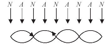
standing wave is defined as the summation of two waves of the same frequency
traveling in opposite directions in or on the same medium. A medium subjected to
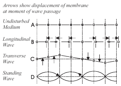
transverse wave energy will exhibit
These reflections, added to and subtracted from the original transverse wave, create multiple resonance nodes. In a musical instrument these resonance nodes are the characteristic voice of the instrument. In a sound reproduction device these nodes add a characteristic voice to any sound reproduced. Intermodulation is introduced into the structure of all waves contained within the membrane as a result of these nodal structures. In addition, the various harmonics of these transverse waves are displaced in both phase and time with relation to new waves. So long as these displaced wave structures exist they continue to add harmonic and intermodulation distortion to any subsequent transverse wave induced into the membrane. Extreme cases of harmonic and intermodulation distortion are often referred to as cone breakup. Thus the elimination of standing waves on any radiating membrane is essential to the reduction of harmonic, intermodulation, phase and time signature distortion of the original transverse waves.
All
kinetic energy transfer between mediums can be classified as boundary layer
physics. A simple description of a boundary layer is the area in or on a medium
where the kinetic energy is changing state or entering a new medium. In a cone
loudspeaker there are minor and major boundary layers. The first
The benefits of eliminating standing waves while increasing energy transfer and phase coherence are synergistic. This synergism allows the economic manufacture of an acoustic radiator with very low transient harmonic, intermodulation and phase / time signature distortion. The specific audible results of treating all surfaces with the EnABL pattern and conformable coating are fourfold. (1.) An increase in discreet source information. Instruments in a reproduced sound field are located exactly with reference to other discreet instruments. This location reference does not shift due to frequency content within the discreet instruments range. Even multiple instruments producing the same information maintain a discreet location, without loss of individual response or coloration of the group sound.
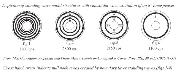
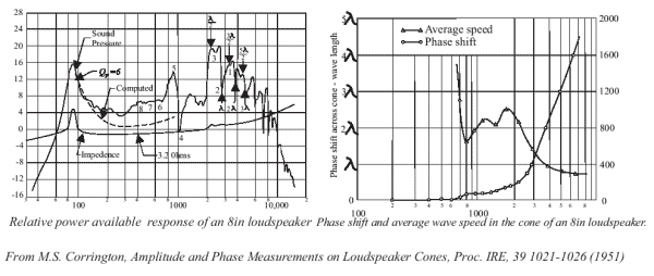
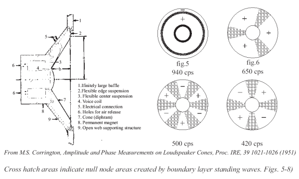
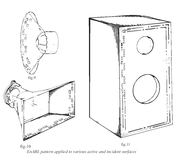
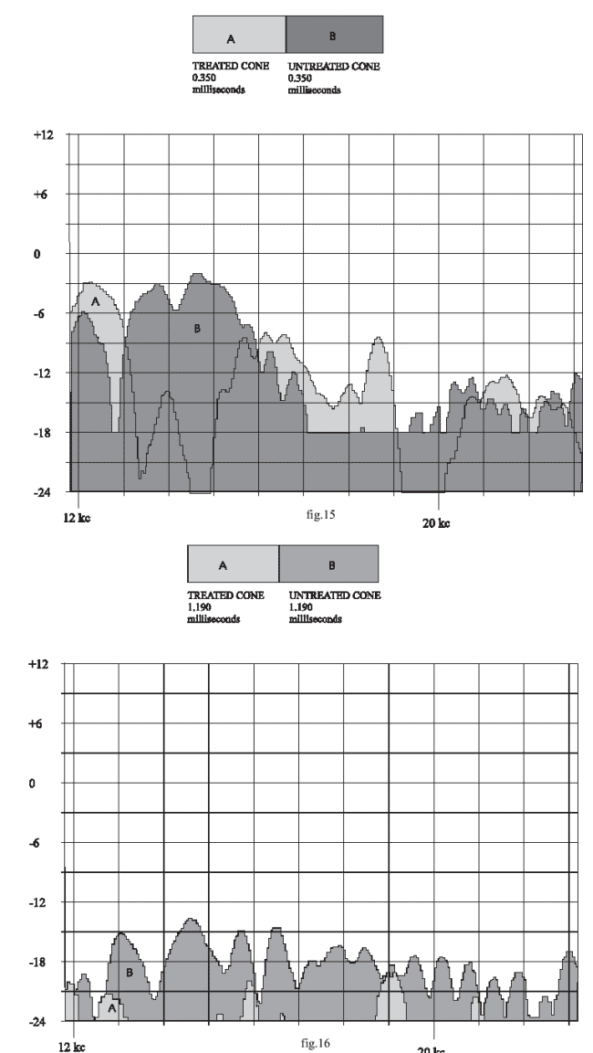
(2.) Elimination of masking caused by bleeding of one perceived sound source into another due to the transient “ringing” of transducers (fig.#16). This effect results from unconstrained skin effect standing waves traversing the transducer after the original transient impulse has been emitted. The resultant sound is an aura of fricative hash around a discreet source in the sound field. This ringing combines with and overlays notes and fricative auras from other discreet sources. This interleaving of fricative sound interferes with time signature recognition and a reduction in depth of field information is the result. (3.) Enhanced dispersion of transient and sinusoidal signals without hot spots. This elimination of localized peak areas of radiated energy is the result of the enforcement of consistent energy density throughout the emitting surface (fig.#14). (4.) Application of the complete process will effectively eliminate transient standing wave induced edge reflections on incident surfaces, commonly referred to as edge diffraction (fig.#s 10 & 11). As air borne longitudinal compression waves cross an incident surface, a skin effect transverse wave is created in the boundary layer and the same energy transfer problems that occur on radiating surfaces are evident at the edges of the incident surface. The EnABL process produces a synergistic effect on adjacent surfaces equivalent to treating the boundary layer of an acoustic radiator. The freeing of transducers from their default condition, as single frequency perfect piston emitters, is a controversial topic at best. As has been shown by Baranek, Corrington, Walsh and others, a transducer emitting frequencies above its diameter / frequency, perfect piston frequency, acts as a transmission line emitter (fig.#s 1,2,3,4 & 5). Below this point an uncorrected device acts as a bending board and must move, as a piston, to emit these lower frequencies. Transducers lose articulation above their perfect piston frequencies due to unconstrained skin effect standing waves on the boundary layer interface. Unconstrained skin effect standing waves also cause a loss of articulation below a transducer’s perfect piston frequencies. All transverse waves, excepting those created purely by longitudinal piston compression acceleration of a transducer membrane, are subject to boundary layer energy transfer corruptions.
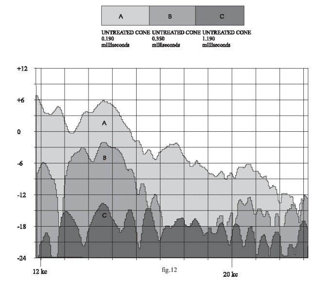
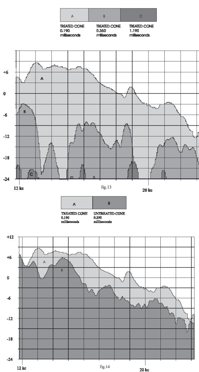
As lower frequencies are emitted a larger percentage of a diaphragm emits a phase compromised nodal area signal (figs. #6,7 & 8). For frequencies well into the bending board range of any transducer, very little area is actually emitting a time or phase correct signal. The EnABL process forces the membrane of a transducer to act as a transmission line until it can no longer bend the energy into the surrounding environment. Thus bass note transient response is no longer dependent upon longitudinal piston compression acceleration of a transducer membrane. This does not mean a transducer reproducing bending frequencies ceases to move. The treated transducers move to allow the completion of a phase coherent bending frequency. Their movement is less at the higher frequency onset of bending emissions and is as great as the movement found in uncorrected transducers at the lowest frequencies. The difference in output comes from greater effective emitting area and less resistance to impulse acceleration in the boundary layer. The low frequency roll off characteristics show a near perfect parabolic response curve on a logarithmic chart, regardless of transducer size. Phase coherence and time signature are maintained to the lowest emitted frequencies. The EnABL pattern and conformable coat process defeat skin effect transient standing wave corruption, enhance the energy content of the boundary layer, and allow impulse waves on the transducer membrane to exceed the speed of sound through air. These attributes allow virtually massless acceleration of a transverse wave within the boundary layer. A phase coherent flat wave emission, without time signature blurring, is the result. These claims are demonstrable and measurable. The enclosed frequency response plots are from FFT processing of an .006ms duration square wave pulse test, with gates set at 0.00 and 5.5ms. The driver tested was an inexpensive 1.75"dia. cone tweeter from a three way system. A Neumann microphone was positioned 1" from the tweeter center dome in a free field setup and absorbent baffles covered the other drivers. The same tweeter was used in before and after tests. The initial 0.190ms point was chosen to show the peak of the positive half of the signal, after it exited the outer edge of the cone. The 0.350ms point shows the signal reflected from the bottom end of the voice coil. The 1.190ms point shows the emissions after one complete cycle of standing wave ringing. The extension of the frequency response is a characteristic improvement of inexpensive drivers and is not of concern in a well designed unit. The lack of “drop out” in the 0.019ms response curve of the treated unit is typical of all drivers utilizing the EnABL pattern and conformable coat process. The cessation of transient ringing, at 1.190ms, is also typical and in the case of excellent drivers is often the most audible improvement. Figure #12 shows a complete time domain for the untreated tweeter. Figure #13 shows the complete time domain for the treated tweeter. Figure #14 shows a comparison of before and after treatment at .0190ms..Figure #15 shows a comparison of before and after treatment at 0.350ms.. Figure #16 shows a comparison of before and after treatment at 1.190ms.
All information in this document is covered by U.S. patent # 5,304,746 and all rights are retained.
|

 standing
wave phenomena in harmonic values determined by the initial frequency and the
physical makeup of the medium. A standing wave on a radiating membrane is
created by the arrival, at opposing terminus points, of both original and
reflected waves. If it is more efficient for the energy contained in the
transverse waves to be reflected from a terminus, instead of transferring to a
new medium, this reflection will combine with subsequent transverse waves to
create standing waves.
  Two
distinct standing wave formats exist within drivers. The one inherent to the
driver, due to systemic construction issues, the other is a transient phenomena,
inherent to the boundary layer found on all radiating surfaces. To eliminate
both types of standing waves on a finite medium, the reflections from terminus
points must be removed, or a situation equivalent to their elimination must be
created. The method described here focuses on transients, simulates an infinite
distance between terminus points on the boundary layer and relies upon two
inherent characteristics of transverse waves vibrating a membrane to accomplish
this. The first characteristic is that the initial pass of a transverse wave, in
a membrane, will exhibit transmission line attributes. This indicates that phase
and time signatures will remain coherent from introduction to final terminus.
The second is that transverse waves, whose amplitude will not allow uniform
penetration of a membrane, will exhibit skin effect attributes. This indicates that a wave that does not penetrate a
membrane uniformly will have a center of displacement towards the surface
boundary layer offering the least resistance to coherent transmission.
 is the juncture
between the voice coil and coil former. This a major systemic boundary, because
the energy remains in its original state, a longitudinal compression wave, while
changing carrier medium. The second, the juncture of coil former and cone, is
also major systemic boundary. Here the energy changes both state and carrier
medium, becoming a transverse wave in the cone. The last major boundary layer,
between cone and air, is the most susceptible to corruption and arguably the
most important. The transverse energy is being changed into a longitudinal
compression wave across a boundary between two mediums whose energy density
potentials per unit area are radically different. Since the energy cannot
transfer at unity across
 this boundary layer, a duration in time and space is
required. From this degradation in energy transfer through time come all of the
time related transient nodal dysfunction’s i.e. intermodulation, harmonic and phase / time signature
distortions available as transient phenomena, in this boundary layer. As a
transverse wave crosses an acoustic radiator it creates a skin effect pressure
wave in the boundary layer on both sides of the membrane. A large quantity of
the energy creating the transverse wave will have already been transferred into
the environment before reaching the terminus point of the membrane. At the
terminus, a final quantity of energy transfers into the environment and to any
adjacent medium it can enter. The remaining energy reflects in the boundary
layer of the radiating membrane, in skin effect, causing a transient standing
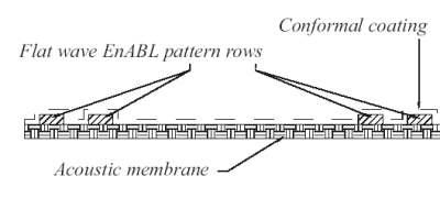
wave. An effective solution to the problem of transient standing waves on
transducers is to apply a low mass pattern of diffraction blocks to the skin
effect surface. This pattern must allow relatively free passage to a transverse
wave in any direction. When placed near a terminus the EnABL pattern eliminates
reflections from the terminus back through the pattern, due to the skin effect
energy density within the pattern openings. The amplitude required for the
energy reflected in skin effect to retraverse the energy gradient, in the
pattern array section of the boundary layer, is too great. The EnABL pattern
will also maintain the original wave structure as it first passes through the
pattern blocks. While the application of this pattern near a terminus is
sufficient to eliminate all forms of boundary layer transient standing waves, a
further refinement to a processed membrane is possible. This refinement consists
of a self leveling, conformable, coating applied over the surface of the
membrane and pattern. The thin coating increases energy density in the boundary
layer of the membrane and a properly formulated coating will allow the
transverse energy, in skin effect, to exceed the speed of sound through air.
Coating the membrane overcomes phase transfer dislocations, found on all
boundary layers, by allowing a more uniform energy transfer per given area of
radiation.