|
You are reading the older HTML site
Positive Feedback ISSUE
16
Kennedy on Audio: DIY a 26 DHT (Directly Heated Triode) Preamp
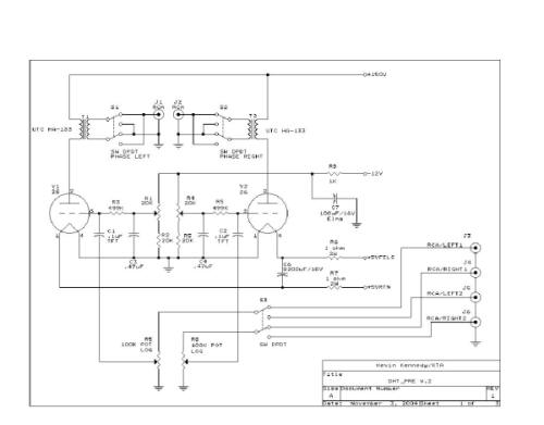
This design is copyrighted and remains the property of Kevin Kennedy/KTA and may be used for noncommercial uses only. For commercial use of any of the circuits presented here, please contact me ([email protected]) for licensing details. Our readers should note that all PFO DIY projects are presented for the edification of our readership, and are published without any representation as to suitability, nor any guarantee or warranty whatsoever from either Kevin Kennedy/KTA or PFO. DIY'ers are reminded that all DIY projects assume a sufficient degree of skill/expertise on the part of the one doing the work, and that damage, accidents or loss may occur. Audio gear assembly/repair also may expose a DIY'er to potentially lethal voltages - PROCEED WITH ALL DUE CAUTION, AND AT YOUR OWN RISK. Caveat lector! Introduction I originally built this pre-amplifier about 4 years ago when I could no longer contain my rampant curiosity regarding the possible performance advantages of Directly Heated Triodes (DHT's) used for this purpose. My original intention was to build something simple and inexpensive to allow me to investigate the possibilities. Since that time the design has evolved slightly and a few minor performance issues have been resolved. The current design is flexible, performs well, and has been very reliable—and perhaps most importantly, I like what I hear. (Insert a grin here.) Interestingly many early DHT's offer excellent linearity without the application of any negative feedback. This characteristic alone would seem to make them ideal for pre-amplifier applications, but in fact there are many practical issues that have discouraged their use. Most early DHT tubes like the 01 and 26 exhibit low mu, operate at substantial plate currents, and have a plate resistance high enough to make their use in simple single stage designs questionable. Some types require weird filament voltages favored for battery operation, and due to their filamentary cathodes AC power is not an option if an acceptable signal to noise ratio is a desired outcome. (Read, "lots of hum.") I chose the 26 for the simple reason that I had a good selection of these DHT's on hand, and a dearth of the 01. The 1.5V filament supply issue did not faze me as I regarded it as a worthy challenge to be overcome in as simple a manner as possible. The 26 and 01 are very similar except for the filament voltage, current, and the maximum plate voltage rating. From an audio performance perspective either of these types should provide exemplary performance. I initially considered an SRPP design using dissimilar triodes, or a cathode follower topology; however, I felt that these were less than optimum solutions, as the additional tubes would impart their own specific sonic signatures and not allow me to accurately assess the virtues of direct heated triodes in small signal applications. Transformer coupling seemed like the solution to at least one of the problems at hand, so to that end a vintage pair of UTC HA-133 plate to line transformers were procured. This transformer was commonly employed in Ampex recording studio equipment, where excellent performance was imperative. The transformer is rated as having a response flat from 30Hz - 20kHz -1dB 1, a maximum rated plate current of 8mA, a primary impedance of 15KΩ, and several possible secondary impedances including 600Ω, which is commonly employed in professional equipment. A permalloy core, split primaries and secondaries as well as relatively good shielding are other features of this device.2 Obviously there is a certain amount of fascination surrounding the application of transformers and DHT's in a line stage to which I was not immune. These primitive designs have an excellent reputation for detail, tonal accuracy, and sheer musicality, attributes which finally overcame my concerns about possible technical obstacles. The design featured here is very customizable, and can be built to suit a wide range of tastes and budgets. Several power supply design options will be discussed, however based on my experience I do strongly recommend that the power supply be built on a separate chassis to avoid hum and noise from the supply getting into the audio circuitry. Bear in mind that this line stage actually has very little overall gain due to the use of transformer coupling. Gain in my prototype is less than 4dB total and will be highly dependant on your choice of plate to line transformer. You may prefer to think of this design as a cross between a passive controller and a very low gain power amplifier. The Sound The pre-amplifier has a definite sonic character, tending to the very slightly warm, mellow end of the spectrum. It is extremely holographic in its imaging characteristics, and has excellent extension into the deep bass and extreme highs. The midrange is—err—"liquid" (nothing else quite describes it. Insert another grin here!) Transients are cleanly and clearly delineated without calling attention to them. The tonal balance is natural. It would be synergistic with a neutral to a somewhat analytical sounding SE amplifier, where its character might tend to balance out the overall sound. (For a suitable SE amplifier design, see my website at www.kta-hifi.net.) Obviously the transformers are playing a role in this, and it is quite likely that the character of the overall sound is more dependent on transformer quality than anything else. I have noted that tube rolling does produce subtle but audible changes in the character of the pre-amplifier, but the differences are not extreme, and any good 26 will do the job. I have tried Radiotron UX-226's, CeCo Globe 26's, (my favorite) Philco's and several others—all with pleasing results. The installation of stepped attenuators recently resulted in a significant improvement in overall resolution, and I recommend them. Overall I would say the sound is quite compelling, the signal path is simple enough that none of the music gets lost along the way. I also recently added switches to allow me to change the absolute polarity of the outputs, and there is material where this addition has been clearly beneficial—unprocessed vocals, choral works and percussion instruments. Disclaimer Hazardous and possibly even lethal voltages are present in this design. No responsibility will be taken for the ability or inability to use this information safely. This article is intended for those with some construction experience and knowledge of what constitutes safe construction and operating practices. Design Considerations Being originally somewhat budget-minded orientation on this project, I choose to use as many junk box components as I could muster. A surplus encapsulated supply was used to provide both bias and filament power. Any supply that can provide at least 2 - 3A @ 5.0V and -12V or -15V @ 100mA will serve nicely. For those who are more ambitious or just don't have the requisite supply in their junk box, several other options will be mentioned below. The sockets are inexpensive Russian made ceramic jobbies with gold plated contacts and have not caused any problems in 4 years. There are some wonderful NOS, not to mention new sockets available, for those inclined to spend the money. The 26 filaments are operated in series using a regulated 5V supply with dropping resistors to reduce the voltage to 3V for the filaments... Despite the common filament connection cross-talk between channels has not been a problem. I will detail several filament supply options that do not require the use of surplus power supplies, as well as what is required to use the 01, and its variants. While cathode bias is possible with this design, I felt that sharing a common bias resistor and capacitor was a design compromise I did not want to make. Early DHT types are actually well suited to fixed bias operation. Some will choose to bias their tubes with 9V batteries which will provide excellent service, and approximately the right bias voltage; however they do need to be changed periodically as their internal impedance increases with age. I felt that I wanted a "use and forget" sort of design not requiring periodic maintenance… (Hopefully, anyway…) Batteries do have a major advantage in that they are entirely free of noise and ripple; however I prefer a well filtered and regulated bias supply which allows a wide bias adjustment range to optimize performance. A fully regulated plate supply is featured in this design to assure consistent performance and low noise. The basic regulator design is quite simple and uses readily available parts. A carefully selected neon lamp can be substituted for the zener reference; however, feedback resistors will need to be adjusted in value to compensate for the change, and it is left to the accomplished reader to determine the correct values for the neon in hand. Most pre-amplifier designs use some minimum level of local or global feedback, but this design does not and is only practical due to the inherent linearity of the tube chosen. Performance is excellent in every sense; however, certain precautions are required in the layout and construction of this design as both the transformers and the tubes are susceptible to electrical noise pick up. Technical Details The pre-amplifier topology is a zero feedback common cathode direct heated triode stage transformer coupled to the load. It is essentially a low gain power amplifier with a voltage gain of under 4dB. Overall voltage gain is determined by the mu of the triode which is ~8 for both the 01 and the 26, the winding ratio of the plate to line transformer chosen, and the load impedance of the driven power amplifier. The output polarity of each channel is switchable in order to address absolute polarity issues which are sometimes audible in my system. They may be included or omitted as the builder desires.
Bias the 26 to approximately 6 or 7mA which is roughly equivalent to –9V grid bias. Measure the DCR of the output transformer and then set the bias to drop the appropriate voltage across the transformer primary where I=E/R, where I is the desired bias current, E is the voltage measured across the primary and R is the measured DCR. See the table below for the characteristics of the DHT of your choice:
Transformers having a primary impedance of 10KΩ to 20KΩ may be employed with good results; however the higher the primary impedance the less the available gain. Any transformer chosen should have a primary inductance in excess of 200H at the desired operating current if good low frequency response is to be maintained. Note also that the gain will be influenced by the load impedance reflected back to the primary of the transformer. In most instances these designs are intended to drive fairly high input impedances; note that gain decreases and distortion increases significantly as the load impedance approaches 600Ω, and 10K and higher load impedances are recommended for this reason. The table below provides estimates of voltage gain, and source impedance for a variety of transformer primary impedances and a secondary impedance of 600Ω. The effects of DCR are neglected and will reduce gain slightly, and increase output impedance as well. Note that due to the high effective load impedance appearing at the tube's plate the available gain will very closely approach mu, provided that the load impedance reflected from the secondary is ~infinite. This table assumes an infinite load impedance—in practice, anything over 100KΩ will result in performance very similar to the values noted. Measurement of the prototype indicate it agrees closely with the prediction for 15KΩ primary impedance.
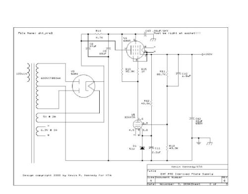
Power Supplies The power supplies must all exhibit extremely low noise levels, with the filament and bias supplies being the most critical. Plate Supply The plate supply utilizes a power transformer providing a center tapped secondary of 600VCT minimum to 700VCT at 50mA. Rectification is provided by a GZ32 or GZ34/5AR4 which is overkill for the amount of current required, but provides long warm up delays to prevent possible cathode stripping in the pass element and most importantly in the DHT's themselves. It's also readily available and inexpensive—a consideration. The plate supply shown is of relatively conventional practice (for me LOL) with a few minor adjustments to allow operation at low output voltages. The 6BQ5 series pass tube is operated as a pentode in order to maximize RP and thereby present a high series impedance to noise on the raw supply. Note that as shown in the schematic, it is crucially important to bypass the screen grid of V4 at the socket in order to prevent VHF oscillations. If the power supply is built in a separate chassis, as I recommend, there should be only one chassis grounding point with all ground connections brought back to this point. I also recommend that the center tap of the power transformer be brought directly to the negative side of the filter caps, and from there go to the star ground—this keeps cap charging currents out of the ground wiring. The error amplifier is a paralleled 12AX7A and the reference is a bootstrapped 51V zener. The dc closed loop gain is about 10dB which provides an output of 150V. The entire 34dB of open loop gain is available for reducing AC output impedance and for reducing output noise. Typical noise levels on the output with good layout should be ≤5mVpp.
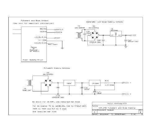
Choosing your DHT… By this point you will need to decide which DHT you wish to use as the filament supply configuration will differ significantly depending on the choice you make. The brick option will allow use of either tube type, but is a less than ideal solution for use with the 01 tube if there is any significant amount of noise present on the supply output. The "Brick" Option Several options exist for the filament regulator circuitry; the simplest is to utilize a surplus brick type power supply.3 Which is an excellent approach for use with the 26 tube. These usually come with a 5V supply at several amps, and a ±12V or ±15V supply at a few hundred mA to operate op-amps. If you wish to use one of these supplies to provide bias voltage it is essential that the 5V supply be completely independent of the other supplies with a separate & independent ground return. The 26 filaments are operated in series using a regulated 5V supply with dropping resistors to reduce the voltage to 3V to operate the filaments. The supply must float, as only the junction between the two tube filaments is grounded. Some additional filtering is provided by a large electrolytic capacitor connected across the filaments.
In the case that a brick supply is used, bias may or may not be derived from one of the other outputs. An independent bias supply or batteries may be used if desired. Ripple levels on this supply must be very low, and 0.5mV or less is recommended to prevent audible buzz. 1. I measured a response that was flat to better than ± 0.5dB from 20Hz – 20kHz which indicates that this component was conservatively specified by UTC. 2. Magnetic coupling is always an issue with low level audio transformers and I recommend mounting them as far away as possible from power transformers and other AC wiring. 3. These supplies are made by Acopian, Kepco and others. Fully encapsulated these units were intended for instrumentation, test equipment and other similar purposes. Both linear and switching supplies are available, if a switching based unit is used the 5V output must be loaded in order for the regulator to function properly. I recommend linear based supplies if available.
Battery Bias If you wish to use batteries for bias, simply delete the pots R1 and R4, then connect the 9V batteries directly to R3 and R5 respectively. Connect the negative side to the resistors and positive to ground. Leave C3 and C4 in place. Use one battery per channel for best results and note that the batteries will require infrequent replacement, perhaps once every couple of years or so. No other bias supply is necessary in this case. Optional Bias Supply This will be necessary if the optional filament supply design is used in place of the brick. See the provided schematic for details. The 7912 series regulator will provide adequate noise performance as there is additional low pass filtering between the supply and the grid bias pots. Optional Filament Supply A constant current filament supply may be used if desired, and is shown in the filament and bias supply options schematic. Two independent filament supplies are required, one for each tube. Do not ground the filament supply in the power supply chassis. Simply delete C6, R6, and R7, connect FILS+ to pin 1 and FILS—to pin 4 of the respective DHT. Connect pin 4 of each DHT to chassis ground in the pre-amplifier through a 10Ω resistor which will also allow you to measure and set the bias more accurately (and safely.) The values shown in the schematic are intended for use with the 26, however alternative values are given for operation with the 01. The monolithic regulators should be TO-220 types and must be adequately heatsinked. For adequate performance the voltage across each regulator should be no less than 3.5V. Dual secondary transformers are readily available from Allied Signal and other manufacturers. Using 01's in place of 26's Use the optional filament regulators and substitute the component values listed in the schematic notes. These will furnish 5V @ 250mA for the filaments, and the socket connections are as noted above for the 26. In addition change R11 in the plate supply to approximately 78.7KΩ to reduce plate voltage to a safe value for the 01. Bias should be set so that the plate current is approximately 3mA per tube. (Roughly –9V at the grid.) Other Construction Details I built my prototype on a single chassis, however unless you use a particularly large chassis I definitely recommend you not follow my lead on this one. I had particular problems with hum pick up in the left channel audio transformer which necessitated its relocation. Stray fields from the power transformer were also picked up by the 26's, a problem only resolved by installing a shield can over the power transformer. Layout is relatively non-critical; however, keep the wiring between the grids, coupling caps and input attenuators/pots as short as possible. Should high frequency oscillation be noted add a 1KΩ grid stop resistor right at the socket on each DHT. These were not necessary in my unit; lead lengths in the prototype including the capacitor body is under 1.5". I seriously recommend the use of separate chassis in the construction of this design. All input connectors should be isolated from chassis and a ground buss or star grounding scheme should be used with only one connection to the chassis. Despite the choice of a surplus brick for filament and bias supply, the balance of components were all of high quality. A conventional volume pot may be used; however, I really recommend the use of good quality stepped attenuators if you feel so inclined. I used a pair of ladder type stepped attenuators I purchased from Michael Percy a few years ago. The solitary coupling capacitor is a REL TFT type, but paper types may also be employed. Output transformers should be mounted close to the individual tube to which it is connected, and far away from anything that produces a magnetic field. In the likely case that you are using a transformer other than the specified HA-133 it is important to assure that the transformers provide some level of magnetic shielding to reduce induced pickup. Here is the parts list for the version most like what I built; it assumes the use of the aforementioned surplus power supply "brick." Pre-Amplifier Parts List Item Quantity Reference Part 1 - 2 C1, C2 .1uF/400V TFT 2 - 2 C3, C4 .47uF/100V Film 3 - 1 C6 8200uF/10V 4 - 1 C7 100uF/16V ELNA Cerafine 5 - 1 C8 47uF/450V min 6 - 1 C9 68uF/450V min 7 - 1 C10 1.0uF/200V SCR Film 8 - 1 C11 2.2uF/400V Axon or SCR Film 9 - 1 C12 22uF/630V SCR Film 10 - 6 J1-J6 VAMPIRE RCA JACK 11 - 4 R1, R2 20K POT 10% 1-2W Locking 12 - 2 R4, R5 20K 1% 1/2W MF 13 - 2 R3, R5 499K 1% 1/2W MF 14 - 2 R5,R8 100K VOLUME POT 15 - 2 R6, R7 1 ohm 1 % 2W 16 - 1 R9 1K 1% 1/2W MF 17 - 1 R10 90.9K 1% 1/2W MF 18 - 1 R11 88.7K 1% 1/2W MF 19 - 2 R12, R13 49.9K 1% 1/2W MF 20 - 1 R15 1K, 5% 1/2W Carbon Film 21 - 3 S1, S2, S3 SW DPDT 22 - 2 T1,T2 Plate to Line Transformer 15K: 600Ω UTC HA-133 or Equiv. (See Text) 23 - 1 T3 Transformer 600VCT @ 50mA, 5V @ 2A, 6.3V @ 2A 24 - 2 V1,V2 26/226 25 - 1 V3 GZ32/34 or 5AR4 26 - 1 V4 6BQ5/EL84 (JJ) 27 - 1 V5 12AX7LPS (Sovtek) 28 - 1 D1 Zener, 51V, 5% or NE2H Neon bulb (See text) 29 - 1 PS1 Kepco or Acopian Brick 5V at 2A or greater, with 12V bipolar supply. 30 - 1 CPC1 9 pin Male/Female CPC for inter-chassis umbilical cable. Notes Optional components shown in the filament and bias supply schematic are not listed here. Many of the components required to build this project are available from Digikey, Mouser, Antique Electronic Supply and others. This design is copyrighted and remains the property of Kevin Kennedy/KTA and may be used for noncommercial uses only. For commercial use of any of the circuits presented here, please contact me ([email protected]) for licensing details.
|