|
You are reading the older HTML site
Positive Feedback ISSUE
14
Brickwall Digital Filters and Phase Deviations
in Digital Audio
Reprinted by permission of Gene DellaSala, Editor of Audioholics, www.audioholics.com Over the years controversy has raged back and forth on whether brickwall filters used in digital audio have phase shifts. Audio critics, pundits and assorted experts have gone back and forth on this issue with out much resolution as I can gather. Some companies have put out their so-called solutions to this problem. It is my desire that this article will put this issue to rest once and for all. The predominant type of digital filter used in audio is called an FIR (Finite Impulse Response) filter. The stated frequency response in most data books is a flat frequency response to 20.0kHz and anywhere from –6dB to –12dB down at 22.05kHz. The frequency 1/2*Ts (where fs = 1/2*Ts, fs = sampling frequency, Ts = sampling period) known today as the Nyquist frequency and the Shannon sampling frequency, corresponds to the highest frequency at which a signal can contain energy and remain compatible with the Sampling Theorem. High-quality sampling systems ensure that no aliasing occurs by deleteriously lowpass filtering the signal (cutoff frequency being slightly lower than the Nyquist frequency) before sampling. At 24kHz a typical high performance digital filter for this application is typically greater than –100dB down. As we can see from these numbers, that’s a really stiff slope, and most of us with some analog electronics or speaker crossover background would immediately say this filter must have a phase shift. But digital filters of this type are different from analog filters in one major respect. The FIR filters that are used in digital audio have "uniform group delay". Now if we think about that for a minute we start to realize that if a filter has uniform group delay, than there can be no phase shift in the pass band (The pass band is where the frequency response is flat). For more information on FIR filters, their uniform phase response and lack of "phase distortion" touted by many self proclaimed audio experts, read: www.dspguru.com/info/faqs/fir/props.htm. Since words are generally meaningless to most people it’s appropriate and necessary to support this fact with some oscilloscope photos to illustrate things more clearly. The following tests come from the Philips test CD, Audio Signals disc 1. This disc contains close to 100 different signals for testing CD players and outboard DAC’s. The description of the test is as follows: "Tracks 74 & 75; A 1 kHz sine wave is recorded on one channel (black trace) while the frequency on the other channel is 20kHz (green trace). These sine waves are coherent, whereby both have zero crossings at the same moment. This can be monitored by displaying both signals simultaneously on the same oscilloscope screen. If the player exhibits no phase difference between the two channels, the up going as well as the down going zero crossing of the 1kHz signal should coincide with the up going zero crossing of the 20kHz signal"
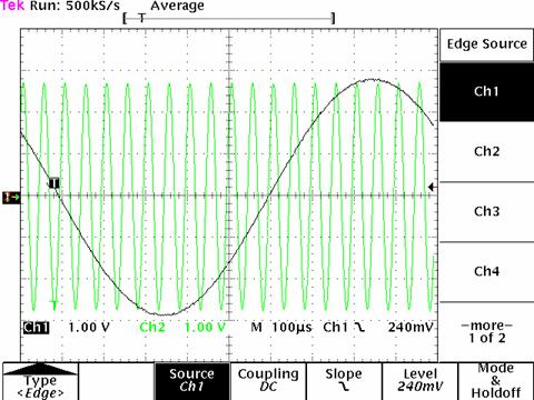
Black Trace: 1kHz Sine Wave Green Trace: 20kHz Sine Wave The scope photo shown above has the right channel in black with our 1kHz sine wave and the left channel in green with our 20kHz sine wave. If you look carefully the zero crossover points line up exactly, and if you wish to count you will find for every cycle of our 1kHz sine wave you will find 20 cycles of the 20kHz sine wave.
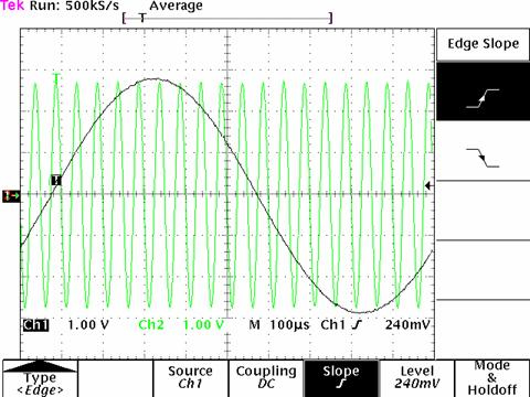
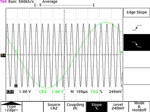
Black Trace: 20kHz sine wave Green Trace: 1kHz Sine Wave The scope shot above is the reverse of the first test. The right channel is in black with a 20kHz sine wave and the left channel is in green with a 1kHz sine wave. Note that the zero crossover points are still lined up exactly. We should also note that in each of the above scope photos that the 20kHz sine wave is at a slightly lower amplitude than the 1kHz sine wave. Once again from our traditional analog electronics background and loudspeaker crossover background we should expect the 20kHz sine wave to be out of phase, but as we can see this appears not to be the case. In the great bulk of CD players and outboard DAC’s, an active low pass filter is used to smooth out the waveforms coming out of the DAC chip. One of the great properties of some types of active filters is that they will not introduce phase shifts in the band of interest. The two most commonly used for this application are Bessel and GIC active low pass filters. The one used for this converter is a GIC filter. I should also note that the unit tested has a standard 8 times over sampling FIR digital filter. There is no up sampling in this unit. The reality of this situation, due to the lack of phase shift problems from FIR filters especially with supplementary low pass active filters and over sampling of CD digital playback systems, is that the next time you read some self proclaimed audio expert (usually on internet forums) stating that up sampling reduces problematic phase shifts of standard 44.1kHz/16bit PCM audio, or some manufacturer claiming to have the magic digital antidote for phase shift in digital audio, take it with a grain of salt and point them to this article. In addition, over the years I have had numerous CD players and outboard DAC’s on my bench for test. The have been only two players that failed this test. One that was "modified" from the original unit, and the modification was done in the low pass filter section after the DAC. The "modification" caused the unit to be 7.5dB down at 20kHz and a pronounced phase shift at 20kHz. The second unit was a very old unit dating from the early 1980’s that had no over sampling and an analog brickwall filter used for the low pass filter. This type of design was discontinued close to 20 years ago, and for good reason. For more information on over sampling: www.earlevel.com/Digital%20Audio/Oversampling.html The following four scope photos are expanded versions of the two used above.
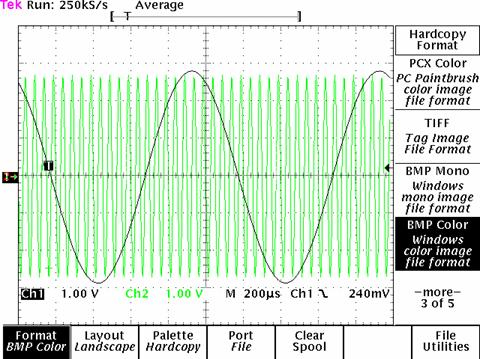
Black Trace: 1kHz Sine Wave Green Trace: 20kHz Sine Wave Notice the perfect Sine Wave reproductions with no phase anomalies or distortion. At 20kHz we see a decrease in amplitude of about 100mVpp which represents about 0.1dB loss and is very common for a CD player with a FIR filter located slightly above ½ the Nyquist frequency (44kHz/2 = 22kHz).
Black Trace: 1kHz Sine Wave Green Trace: 20kHz Sine Wave
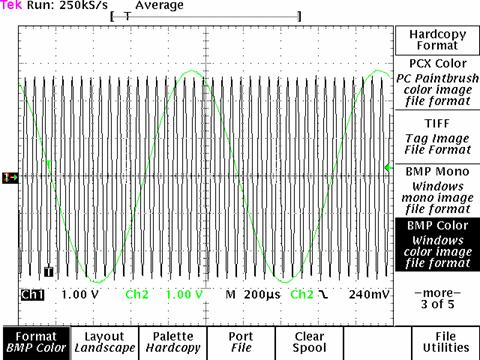
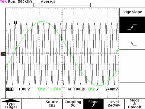
Black Trace: 20kHz Sine Wave Green Trace: 1kHz Sine Wave Notice between every low and high peak of the 1kHz signal, there are 10 low and high peaks of the 20kHz signal. If we were to expand this out to one full period, there would be 20 samples of the 20kHz for every 1 sample of the 1kHz signal. Mathematically this is an exact ratio between a 1kHz and 20kHz signal. If there were phasing problems due to the FIR filter, this would not be possible to achieve.
Black Trace: 20kHz Sine Wave Green Trace: 1kHz Sine Wave Approximately 5 years ago I submitted to the audio magazine Bound For Sound copies of the first two scope photos, due to the fact that the editor/publisher was talking about "digital phase" in a number of his articles. The editor/publisher told me over the phone that a number of so called "experts" that he talked to said just the opposite about the "digital phase" issue. My reply was when they send me the scope photos I'll believe them. I'm still waiting. Incidentally, the editor/publisher of Bound for Sound never published those scope photos or offered to let me write an article countering those claims. I am truly thankful that Audioholics has allowed me to write this article and publish it on their web site.
Dan Banquer For responses to this article, read the Reverberations or letters page.
|